


10
STEP 12 —Check Charge
Factory charge and charging method are shown on unit rating
plate. To check char ge in cooling mode, refer to Cooling Only
Procedure. To check charge in heating mode, refer to Heating
Check Chart Procedure.
Cooling Only Procedur
e
NOTE: If subcooling charging conditions are not favorable,
charge must be weighed in accordance with unit rating plate,
±0.6 oz./ft. of 3/8--in. liquid line above or below 15 ft.,
respectively. Favorable conditions fall within the ranges given on
the charging chart on the outdoor unit plate.
This system requires charging by the subcooling method.
1. Operate unit a minimum of 10 minutes before checking
charge.
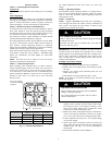
2. Measure liquid service valve pressure by attaching an
accurate gage to service port.
3. Measure liquid line temperature by attaching an accurate
thermistor type or electronic thermometer to liquid line
near outdoor coil.
4. Refer to unit rating plate for required subcooling
temperature.
5. Refer to Table 3. Find the point where required subcooling
temperature intersects measured liquid service valve
pressure.
6. To obtain required subcooling temperature at a specific
liquid line pressure, add refrigerant if liquid line
temperature is higher than indicated or reclaim refrigerant
if temperature is lower. Allow a tolerance of ± 3°F.
Heating Check Chart Procedur
e
To check system operation during heating cycle, refer to the
Heating Check Chart on outdoor unit. This chart indicates
whether a correct relationship exists between system operating
pressure and air temperature entering indoor and outdoor units. If
pressure and temperature do not match on chart, system
refrigerant charge may not be correct. Do not use chart to adjust
refrigerant charge.
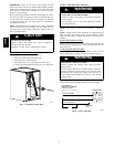
STEP 13 —Final Checks
IMPORTANT: Before leaving job, be sure to do the following:
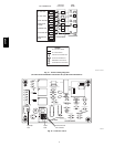
1. En sure that all wirin g is routed aw ay fro m tu bin g and
sheetmetal edgestopreventrub--through or wire
pinching.
2. Ensure that all wiring and tubing is securein unitbefore
addin g p an els an d co v ers. S ecu rely fasten all panels and
covers.
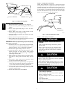
3. Tighten serv ice valv e stem caps to 1 /1 2--turn p ast fin g er
tight.
4. Leave UsersManual with owner. Explain system
operation and periodic maintenance requirements outlined
in manual.
5. Fill out Dealer Installation Checklist and place in
customer file.
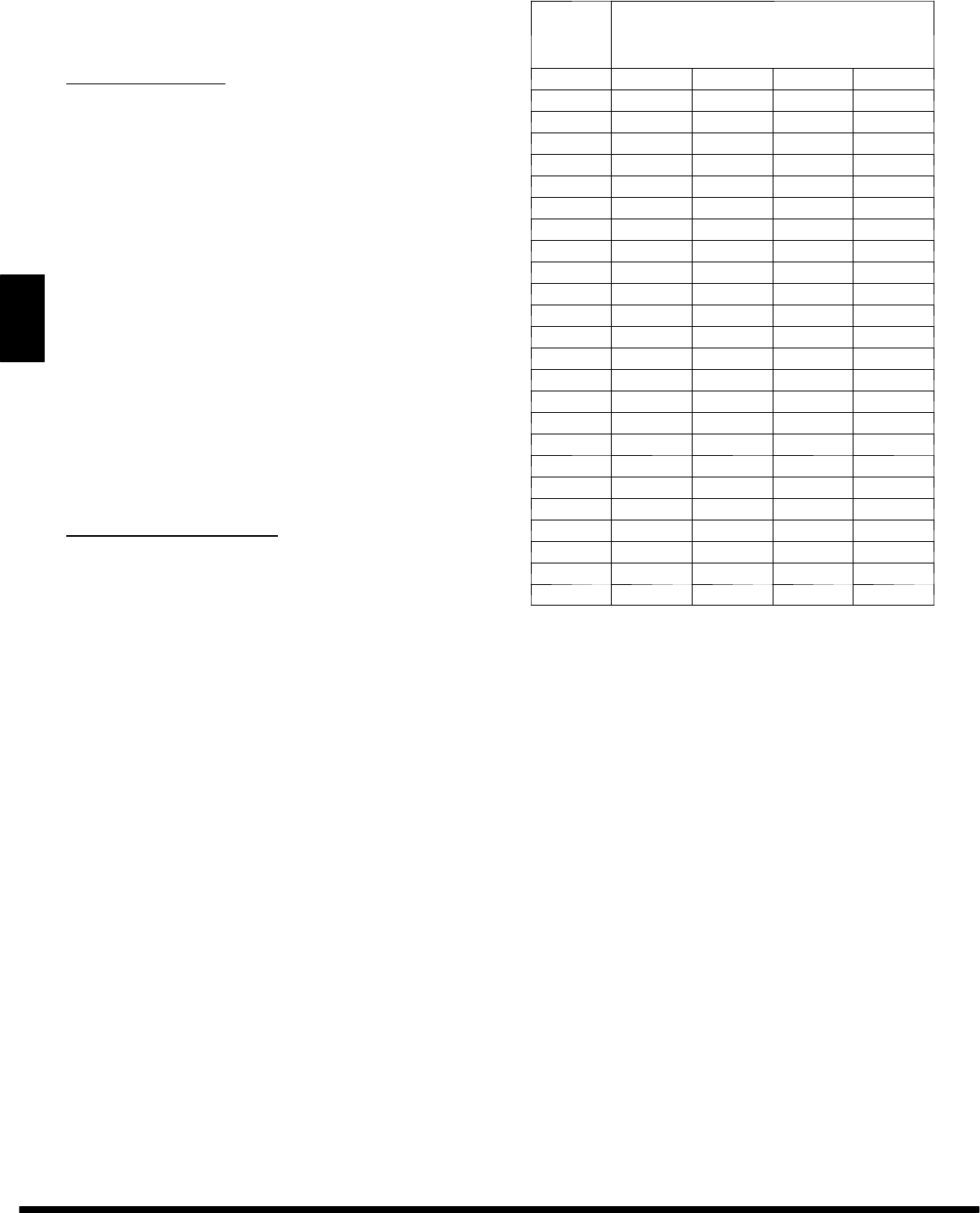
Table 3—Required Liquid--Line Temperature
Liquid
Pressure
at Service
Valve
Required Subcooling Temperature (°F)
(PSIG) 5 10 15 20
134 71 66 61 56
141 74 69 64 59
148 77 72 67 62
156 80 75 70 65
163 83 78 73 68
171 86 81 76 71
179 89 84 79 74
187 92 87 82 77
196 95 90 85 80
205 98 93 88 83
214 101 96 91 86
223 104 99 94 89
233 107 102 97 92
243 110 105 100 95
253 113 108 103 98
264 116 111 106 101
274 119 114 109 104
285 122 117 112 107
297 125 120 115 110
309 128 123 118 113
321 131 126 121 116
331 134 129 124 119
346 137 132 127 122
359 140 135 130 125
CARE AND MAINTENANCE
For continuing high performance and to minimize possible
equipment failure, periodic maintenance must be performed on
this equipment.
Frequency of maintenance may vary depending upon geographic
areas, such as coastal applications. See Users Manual for
information.
Copyright2006CarrierCorp.S 7310W.MorrisSt.S Indianapolis,IN 46231
Manufacturerreserves therighttochange,atany time,specifications anddesigns withoutnoticeandwithoutobligations.
Catalog No: 25HCR-- 2SI
Replaces:25HCR--1SI
Printedin U.S.A. Edition Date:02/06
25HCR