


5
Outdoor units may be connected to indoor section using
accessory tubing package or field--supplied refrigerant grade
tubing of correct size and condition. For tubing requirements
beyond 80 ft., substantial capacity and performance losses can
occur. Following the recommendations in the Application
Guideline and Service Manual--Residential Split--System Air
Conditioners and Heat Pumps will reduce these losses. Refer to
Table 1 for accessory requirements. Refer to Table 2 for field
tubing diameters.
There are no buried--line applications greater than 36 in.
If refrigerant tubes or indoor coil are exposed to atmosphere, they
must be evacuated to 500 microns to eliminate contamination and
moisture in the system.
Outdoor Unit Connected to Factory --Approved Indoor
Unit
Outdoor unit contains correct system refrigerant charge for
operation with approved ARI rated indoor unit when connected
by 15 ft. of field--supplied or factory--accessory tubing, and
factory supplied filter drier. Check refrigerant charge for
maximum efficiency.
Refrigerant Tubing and Sweat
Connections
Connect vapor tube to fitting on outdoor unit vapor service
valves (see Table 2). Connect liquid tubing to adapter tube on
liquid service valve. Use refrigerant grade tubing.
CAUTION
!
UNIT DAMAGE HAZARD
Failure to follow this caution may result in equipment
damage or improper operation.
Service valves must be wrapped in a heat--sinking
material such as a wet cloth while brazing.
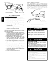
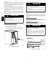
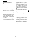
Remove plastic retainer holding outdoor piston in liquid service
valve, leaving the piston and piston retainer inside the valve.
Connect sweat/flare adapter provided, to valve. (See Fig. 6.)
Connect refrigerant tubing to fittings on outdoor unit vapor and
liquid service valves. Service valves are closed from factory and
ready for brazing. After wrapping service valve with a wet cloth,
tubing set can be brazed to service valve using either silver
bearing or non--silver bearing brazing material. Do not use soft
solder (materials which melt below 800°F). Consult local code
requirements. Refrigerant tubing and indoor coil are now ready
for leak testing. This check should include all field and factory
joints.
PISTON BODY
PISTON
PISTON
RETAINER
SWEAT/FLARE ADAPTER
A05226
Fig. 6 --- Liquid Service Valve
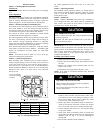
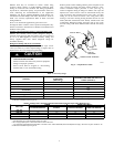
Table 1—Accessory Usage
Accessory
REQUIRED FOR LOW---AMBIENT AP-
PLICATIONS
(Below 55 °F)
REQUIRED FOR LONG LINE APPLICA-
TIONS* (Over 80 ft.)
Crankcase Heater Yes Yes
Evaporator Freeze Thermostat Yes
No
Winter Start Control Yes
No
Accumulator No
No
Compressor Start Assist Capacitor and Relay Yes
Yes
Support Feet Recommended
No
Liquid Line Solenoid Valve No See Long---Line Application Guideline
* For Tubing Set lengths between 80 and200 ft. horizontal or 20 ft. vertical differential (250 ft. Total Equivalent Length), refer to the LongLine Guidelines for Air
Conditioners and Heat PumpsusingR--- 22.
Table 2—Refrigerant Connections and Recommended Liquid and Vapor Tube Diameters (in.)
UNIT SIZE
LIQUID VAPOR (up to 80 ft.*)
Conne ction Diameter
Tube
Diameter
Conne ction Diameter Rated Tube Diameter
018, 024
3/8 3/8 5/8 5/8
030, 036
3/8 3/8 3/4 3/4
042, 048
3/8 3/8 7/8 7/8
060
3/8 3/8 7/8 1--1/8
Notes:
1. Tu be diameters are for total equivalentlengthsup to 80 ft..
2. Donot apply capillary tube or fixed orifice indoor coils to these units.
* For Tubing Set lengths between 80and 200 ft. horizontal or 20 ft. vertical differential (250 ft.Total Equivalent Length), refer to the Longline Guideline --- Air
Conditioners and Heat PumpsusingR--- 22
25HCR25HCR