


4
INSTALLATION
1. Inspect package contents for missing or damaged parts.
File a claim with the shipping agency if parts are
damaged and notify your local Carrier representative if
any item is missing.
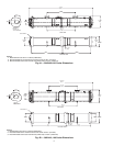
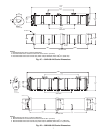
2. Determine the new location for the cooler. Ensure that the
new location supports the cooler and economizers
weights and that there is enough room for service access
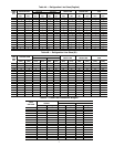
and tube removal. See Tables 4A and 4B to determine
refrigeration line sizes. See Table 5 for cooler and
economizers weights. See Fig. 4A-5B for cooler and
economizers dimensions, tube removal clearances, and
service areas.
3. Open and tag all electrical disconnects.
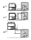
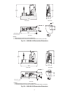
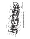
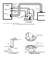
Cooler and Economizer Removal — The cooler and
economizers are accessible from the cooler side of the unit. To
remove the cooler and economizers from the unit, complete the
following steps:
1. Remove refrigerant from all circuits using standard
refrigeration practices. Refer to unit nameplate or installa-
tion instructions for refrigerant quantities.
2. Disconnect the cooler heater wiring, and conduit if
equipped.
3. Remove entering and leaving chilled water temperature
thermistors. Make sure to label thermistors as they are
removed. See Fig. 6.
4. Disconnect and label the chilled water flow switch cable
from the chilled water flow switch located on the leaving
water nozzle. See Fig. 6.
5. Disconnect the suction pressure transducer cables from
the transducers. Make sure to label cables as they are
removed. See Fig. 6.
NOTE: The suction pressure transducers (SPT) do not neces-
sarily need to be removed. However, use care in protecting the
SPTs throughout the removal and remote installation processes,
as the SPTs are an important part of the remote installation.
6. Disconnect the electronic expansion valve (EXV) cables
from the EXVs at each economizer. Make sure to label
cables as they are removed. See Fig. 6.
NOTE: The 30XA080 units do not utilize an economizer.
In this case, only the EXVs are present.
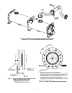
7. Unbolt the cooler suction flanges from the cooler. Tempo-
rary supports may be needed to support the suction pipes.
See Fig 6.
8. At each circuit’s economizer, cut the liquid lines going to
the economizer assembly before the manual shutoff valve
(see Fig. 6, cut 1, circuits A and B). Cut the cooler liquid
lines between the manual shutoff valve and the cooler
(see Fig. 6, cut 2, circuits A and B). Cut the economizer
lines between the manual shutoff valve and the sensors
(see Fig. 6, cut 3, circuits A and B).
9. Remove the screws from the feet of each economizer.
Save all of the screws. Remove the economizers by care-
fully sliding them out the cooler side of the unit.
10. Remove the screws from the cooler feet. Save all of the
screws. Slide the cooler slightly to the left to clear the
refrigerant tubing.
11. Remove the cooler by carefully sliding the cooler out the
cooler side of the unit.
Shut off all power to this equipment prior to installation.
There may be more than one disconnect switch. Tag all
disconnect locations to alert others not to restore power
until work is completed. Failure to disconnect power from
equipment prior to installation could result in serious
personal injury or death.
Because 30XA systems use polyolester oil, which can ab-
sorb moisture, it is important to minimize the amount of
time that the refrigeration system is left exposed to the at-
mosphere. Minimizing the exposure time will reduce the
amount of moisture that could possibly damage the unit.
The removal instructions minimize the exposure time to
prevent this type of damage. The remote installation in-
structions outline a dehydration process to counteract any
exposure that might have occurred.
Before installation of the field-supplied piping, the piping
must be thoroughly cleaned and free of dirt, debris, oil, and
welding residue. Presence of these objects will cause severe
damage to the compressors or other components of the re-
frigeration system.