


10
Remote Cooler and Economizers Installa-
tion —
Install the cooler and economizers in a remote
location by following this procedure:
NOTE: Throughout the Remote Cooler and Economizers
Installation steps, the two accessory package part no.
(00EFN900003000A, 00EFN900003100A) have been short-
ened to 3000A and 3100A. When a specific part is referred to
in each accessory’s package, the package no. is mentioned fol-
lowed by the item no. For item no. identification and accessory
package contents, refer to Table 2.
1. After removing the cooler from the base unit, strip back
the insulation on the cooler tube sheets (if required) and
use the two large holes in the top corners for lifting.
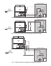
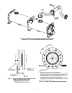
2. Transport the cooler and economizer assemblies to the
new location and secure them into position. Keep the
economizer assemblies as close to the cooler as possible.
Also, ensure there is sufficient room to install and remove
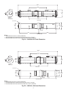
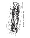
cooler tubes from either end of the cooler. See Fig. 4A-
4D for tube removal clearances.
NOTE: The 30XA080 units do not utilize an economizer. In
this case, keep the EXV as close to the cooler as possible.
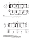
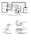
3. Install the accessory-supplied economizer shutoff valves
(3000A or 3100A: Item 1) and liquid line shutoff valves
(3000A or 3100A: Item 2) on the two economizer lines
and liquid lines at circuits A and B on the 30XA base
unit. See Fig. 7.
4. At the new cooler location, connect the field-supplied
cooler liquid line piping between the factory-installed
manual shutoff valve at the two economizer assemblies
and at the cooler. See Fig. 7.
5. Following good piping practices, install additional field-
supplied liquid and economizer line piping in the required
length to reconnect the two economizer assemblies to the
30XA base unit. See Fig. 8 for double suction riser con-
struction detail.
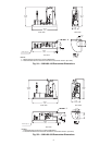
6. For 30XA080-120: all circuits and 30XA140-160: circuit
B, cut the suction pipe (copper) at the 30XA base unit and
discard (see Fig. 6, cut 4, circuit B). Following good
piping practices, install field-supplied copper suction line
piping from the 30XA base unit to the cooler. Use the
accessory-supplied cooler pipe flange (3000A: Item 8),
cooler flange O-ring (3000A: Item 12), and loose pipe
flange (3000A: Item 11) to connect the field-supplied
copper suction line piping at the cooler. See Fig. 9.
NOTE: The original flanges on the cooler and cut from the
30XA base unit may still be usable. However, Carrier recom-
mends and has provided in the accessory kit, parts necessary to
replace both the cooler pipe flange and the suction flange.
When the extended piping is installed, these flanges should be
replaced.
7. For 30XA140-160: circuit A and 30XA180-350: all
circuits, unbolt (DO NOT CUT) the portion of the steel
suction pipes that connected the flex connector flanges to
the cooler at the 30XA base unit and discard. See Fig. 10.
Refer to Table 6 for parts required (field-supplied or
accessory-supplied) to make new connections at the
cooler and the 30XA base unit with the field-supplied
steel suction line. See Fig 11. Follow good piping
practices to install field-supplied steel suction line piping
between the cooler and the flex connector at the 30XA
base unit.
When field-supplied flanges and gaskets are used, an
extra M16 mounting hole must be drilled and tapped to
connect a mounting bracket at the 30XA base unit. See
Fig. 10 and 11 for mounting bracket placement. See
Fig. 12 for mounting hole locations.
If additional gaskets are needed for installation, they must
be
1
/
16
in. non-asbestos fiber with synthetic rubber binder
compressed gasket sheet. An extra mounting hole also
needs to be field modified for any additional gaskets. See
Fig. 12 for mounting hole locations. Field-supplied
mounting nuts and bolts are also needed for field-
supplied gaskets.
8. All of the piping connections are now complete. Leak test
the unit and then pull a deep dehydration vacuum. Con-
nect the vacuum pump to the high-flow access fitting at
the bottom of the cooler, the liquid line service valves,
and the economizer line service valves. For best results, it
is recommended that a vacuum of at least 500 microns
(0.5 mm Hg) be obtained. To perform a standing vacuum
rise test, observe the rate-of-rise of the vacuum in the
system. If the vacuum rises by more than 50 microns in a
30-minute time period, then continue the dehydration
process until the standing vacuum requirement is met.
This will ensure a dry system.
By following this dehydration procedure, the amount of
moisture present in the system will be minimized, and the
factory-supplied filter driers will provide adequate
moisture protection. It is highly recommended that the
filter drier cores be replaced after 24 hours of operation.
This is to ensure that any foreign debris that is captured
during start-up is removed from the system. Additional
moisture removal capacity is also provided.
9. After setup is leak tested and deep dehydration vacuum is
completed, install field-supplied suction and economizer
line insulation between the economizer and the unit. If
necessary, reinstall the insulation on the cooler head.
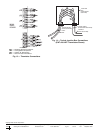
10. To reconnect the EXV cables, use the accessory-supplied
cable assemblies (3000A or 3100A: Item 4). Two cables
are needed for the 30XA080 unit, and four cables are
needed for 30XA090-350 units. Take one cable assembly,
and label both ends with “EXV-A” for the circuit A main
EXV. Then label another three cable assemblies the same
way with “EXV-B”, “ECEXV-A”, “ECEXV-B” for the
circuit B main EXV, circuit A economizer EXV, and
circuit B economizer EXV, respectively (economizer
EXV does not apply to 30XA080 units).
Plug one side of the electrical connectors of the EXV
labeled cables into their corresponding EXV plugs. Run
the cables to the 30XA base unit, and plug the other side
of the cable connectors into their corresponding EXV
leads. Coil excess cables and wire tie in a convenient
location.
11. To reconnect the flow switch cable, use the accessory-
supplied cable assembly (3000A or 3100A: Item 4). Take
one cable assembly and label both ends with “CWFS.”
Plug one side of the electrical connector of the labeled
cable into the flow switch plug. Run the cable to the base
unit, and plug the other side of the cable connector into
the flow switch lead. Coil excess cables and wire tie in a
convenient location.
Do NOT close both manual shutoff valves in one liquid
line. Pressure can build up in the trapped area. To avoid the
possibility of personal injury or property damage, the new
liquid lines between the manual shutoff valves must each
have field-supplied and installed pressure relief valves.