


11
12. Using the accessory-supplied M6 screws (3000A or
3100A: Item 6), install the accessory-supplied junction
box (3000A or 3100A: Item 5) at the desired location
where the entering and leaving water thermistor cables
can be conveniently spliced. One or two knockouts can
be used. Follow all local codes. Remove one knockout
from the junction box and install the field-supplied strain
relief at the knockout hole. If using field-supplied conduit
to provide mechanical protection to the thermistor wires
between the cooler and the 30XA base unit, remove
another knockout.
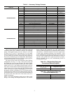
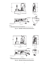
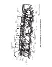
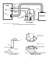
13. To reconnect the thermistors, locate the entering water
thermistor and leaving water thermistor and cut both
leads where they can be spliced in the installed junction
box. Cut, strip, and label both sides of the entering water
thermistor lead “EWT.” Cut, strip, and label the leaving
water thermistor lead the same way, with “LWT” on both
sides. See Fig. 13.
14. Run the labeled thermistor leads connected to the unit
into the installed junction box and tighten the field-
supplied strain relief. Strip back the lead jackets to expose
the two wires in each lead.
15. Take one of the accessory-supplied 5-wire jacketed ca-
bles (3000A or 3100A: Item 3) to connect the thermistor
leads in the installed junction box to the cooler location.
Each wire in the jacketed cable is a different color. Cut
the cable into two pieces so that each has a maximum
length of 100 ft (30.5 m).
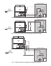
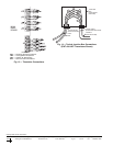
16. Select one jacketed cable and strip back the jacket on
both ends to expose the five wires. Pick any two wires
and label both ends of each wire “EWT.” Pick another
pair of wires and label both ends “LWT.” The fifth wire is
not used. See Fig. 14.
17. Run one end of the accessory-supplied 5-wire jacketed
cable into the installed junction box and splice the identi-
cally labeled thermistor leads. Solder the splices and insu-
late them to prevent shorting. Tighten the field-supplied
strain relief for the cables.
18. Run the other end of the accessory-supplied 5-wire
jacketed cables back to the cooler. Splice the labeled
jacketed cable wires to the matching thermistors. If a
second junction box is necessary at the cooler location,
use the second accessory-supplied junction box (3000A
or 3100A: Item 5).
19. Reinstall the thermistors in the correct cooler wells.
20. To reconnect the suction pressure transducers (SPT),
locate the SPT plugs for circuits A and B, and cut the
leads where they can be conveniently spliced in the
installed junction box at the 30XA base unit. Label the
leads “SPTA” for the circuit A lead, and “SPTB” for the
circuit B lead.
21. Take the two pieces of accessory-supplied transducer
wire harness (3000A: Item 16 or 3100A: Item 14). One
side of the harness is a plug and the other side is three
wires in red, black, and green. Label both sides of one
harness “SPTA,” and label the other harness “SPTB.”
Remove one knockout from an installed junction box and
install a field-supplied strain relief valve at the knockout
hole. If using field-supplied conduit to provide mechani-
cal protection to the transducer wires between the cooler
and the 30XA base unit, remove another knockout.
22. Run the labeled transducer leads connected to the unit
into the installed junction box at the 30XA base unit and
tighten the field-supplied strain relief. Strip back the lead
jackets to expose the three wires, black, red, and white.
23. Run the lead end of accessory-supplied transducer wire
harnesses into the junction box and splice the identically
labeled leads. The red wire should go with red wire, the
black wire with the black wire, and the white wire with
the green wire. Solder the splices and insulate them to
prevent shorting. Tighten the field-supplied strain relief
for the cables and secure the accessory-supplied junction
box cover (3000A or 3100A: Item 6) with accessory-
supplied M6 screws.
24. Run the plug end of the accessory-supplied transducer
wire harness back to the cooler. Connect the “SPTA” plug
into the circuit A transducer. Connect the “SPTB” plug
into the circuit B transducer. See Fig. 13.
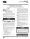
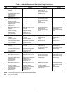
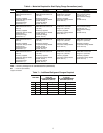
25. Charge the unit to the amount of refrigerant as specified
on the 30XA base unit nameplate. Because of longer
field-installed liquid, economizer, and suction lines, addi-
tional charge is needed. Refer to Table 7 to calculate the
additional charge for each circuit and then add it to the
nameplate charge. Additional charge for the economizer
line is NOT required.
26. Perform all pre-start-up and start-up procedures specified
in the unit operation instructions. Follow the checklist
provided with the unit operation instructions.
27. Verify unit operation.