


15
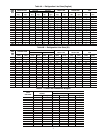
ASME B16.9
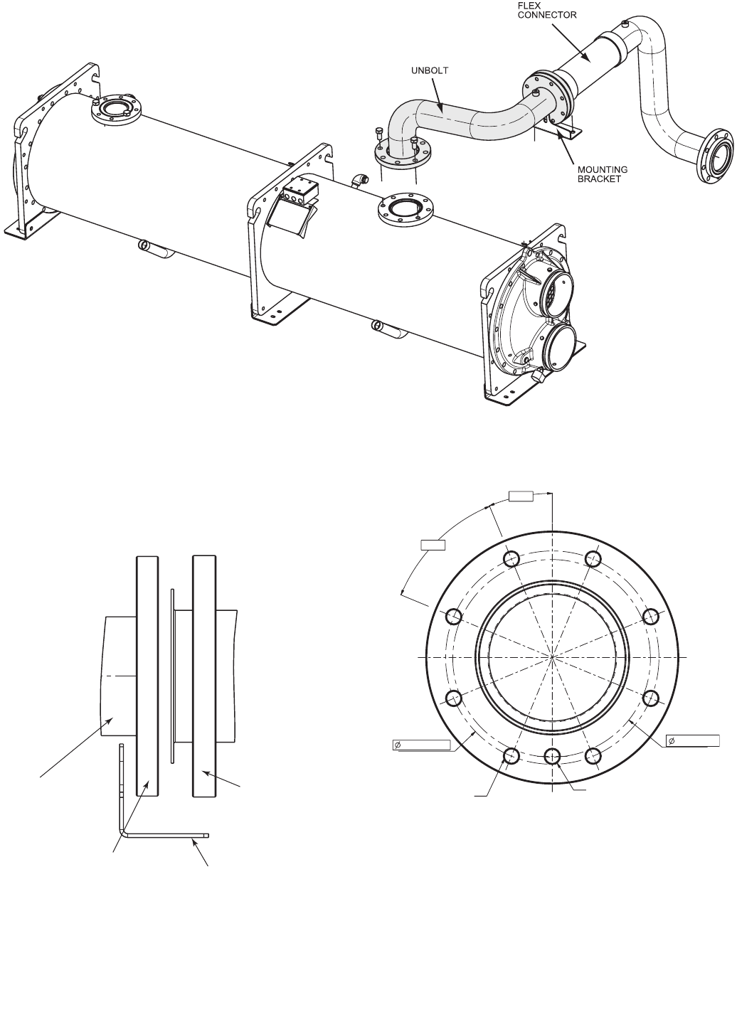
STEEL STUB END
(FIELD-SUPPLIED)
PIPE FLANGE
(ACCESSORY-SUPPLIED,
SEE TABLE 6)
MOUNTING
BRACKET
EXISTING FLANGE
ON FLEX
CONNECTOR AT
30XA BASE UNIT
8 HOLES 1 (25)
EQUALLY SPACED
1 EXTRA HOLE M16
7-7/8 (200)
22.5°
45.0°
8-1/2 (215.9)
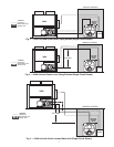
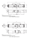
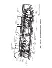
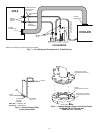
Fig. 10 — Unbolt Portion Between Flex Connector and Cooler
(30XA140, 160: Circuit A and 30XA180-350: All Circuits)
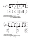
Fig. 11 — Connect Steel Suction Line at the 30XA
Base Unit (Shown) and Cooler
(30XA140, 160: Circuit A and
30XA180-350: All Circuits)
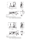
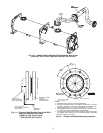
Fig. 12 — Flange and Gasket Mounting Locations
NOTES:
1. Measurements are shown in inches (millimeters).
2. Accessory-supplied flanges and gaskets connecting to the flex
connector: extra hole has been factory-drilled and tapped. See
Table 2 (3000A: Item 10, 14, 15 and 3100A: Item 9, 10, 13).
3. Field-supplied flanges and gaskets connecting to the flex connec-
tor: extra hole must be field-drilled and tapped (M16).
4. The extra hole allows a bolt to slide through and mount the flanges
and gaskets of the suction line on a mounting bracket at the 30XA
base unit. See Fig. 10 and 11.
a30-4521
a30-4522
a30-4523