


2
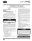
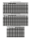
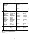
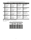
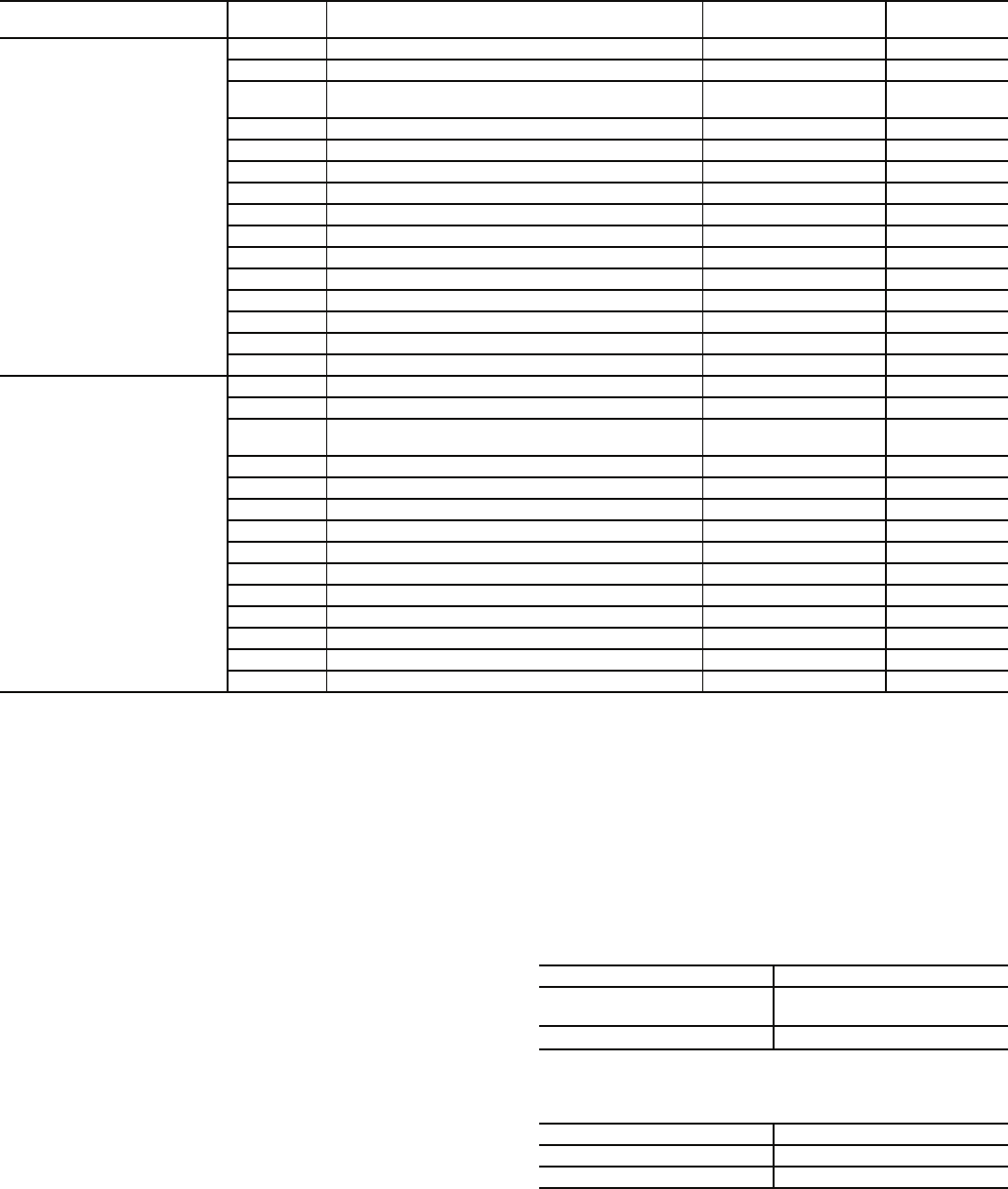
Table 2 — Accessory Package Contents
Choose a space that can support the weight of the cooler and
economizer with service clearances and area for refrigerant
piping. Field-supplied piping must be limited to less than
50 lineal ft (15.25 m) or 75 equivalent ft (22 m) in length.
Suction and liquid line risers must be limited to less than 15 ft
(4.5 m) vertical riser elevation. Suction lines and economizer
lines must be insulated to prevent condensation. Relocating the
cooler introduces minimal line losses if correct piping practices
are followed. Buried lines are not permitted.
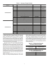
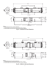
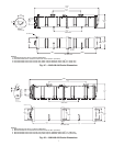
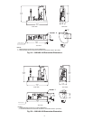
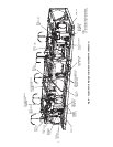
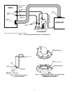
The remote cooler system can be applied in three different
configurations. See Fig. 1-3. In Fig. 1, the remote cooler and
the outdoor unit are at the same elevation. The suction, liquid,
and economizer lines run parallel between the cooler and the
outdoor unit. In Fig. 2, the outdoor unit and remote cooler are
at the same elevation, but the interconnecting piping has an ele-
vation of up to 15 ft (4.5 m) above the base elevation of the
cooler. This could be result of running piping over a wall or
through the ceiling in a building. In Fig. 3, the remote cooler is
located below the outdoor unit. The interconnecting piping has
an elevation of up to 15 ft (4.5 m) above the base elevation of
the remote cooler. This could occur if the remote cooler is in-
stalled in a basement.
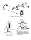
NOTE: Unit 30XA refrigeration piping can be either copper
tubing or steel tubing with flanged connections. All units are
factory charged with compressor oil to the required level.
However, when the double riser is constructed with U-bends or
street elbows, a substantial amount of oil can be trapped in the
U-bend during prolonged minimum load operation. If this
occurs, additional oil is needed to add to the system to prevent
the oil level from dropping below the minimum level in the oil
separator. Add 1 gallon of oil to each circuit. Refer to Controls,
Start-up, Operation, Service, and Troubleshooting Guide for
recommended oil type.
Table 3A — Refrigeration Piping and
Connections Material (English)
Table 3B — Refrigeration Piping and
Connections Material (SI)
ACCESSORY PACKAGE
PART NO.
ITEM NO. DESCRIPTION PART NO. QTY
00EFN900003000A
1 Economizer shutoff valve - 1
1
/
8
in. (29 mm) 00PPG000023501A 2
2 Liquid line shutoff valve - 1
3
/
8
in. (35 mm) EP71BA393 2
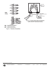
3 5 Wire jacketed cable RM02EJ200
200 ft
(61 m)
4 Cable assembly 32GB404694 5
5 Junction box HX30FZ001 2
6 Junction box cover HX38ZZ001 2
7 M6 Screws 00PPN500000302A 8
8 Cooler pipe flange - 3
1
/
8
in. (79 mm) 00PSN500091400A 2
10 Flex connector flange - 4 in. (102 mm) 00PSG000213300A 2
11 Loose pipe flange - 4 in. (102 mm) 00PSG000205100A 2
12 Cooler flange O-ring KK71EW256 4
13 Flex connector flange O-ring KK71EW250 2
14 Compressor flange gasket - 3 in. (76 mm) 00PPG000011702A 2
15 Compressor flange gasket - 4 in. (102 mm) 00PSG000011703A 4
16 Transducer wiring harness - 100 ft (30.5 m) 00PSN500180500A 2
00EFN900003100A
1 Economizer shutoff valve - 1
1
/
8
in. (29 mm) 00PPG000023501A 2
2 Liquid line shutoff valve - 1
3
/
8
in. (35 mm) EP71BA393 2
3 5 Wire jacketed cable RM02EJ200
200 ft
(61 m)
4 Cable assembly 32GB404694 5
5 Junction box HX30FZ001 2
6 Junction box cover HX38ZZ001 2
7 M6 Screws 00PPN500000302A 8
8 Flex connector flange O-ring KK1EW250 2
9 Compressor flange gasket - 4 in. (102 mm) 00PSG000011703A 4
10 Compressor flange gasket - 5 in. (127 mm) 00PPG000011704A 4
11 Loose pipe flange - 5 in. (127 mm) 00PSG000211900A 2
12 Loose pipe flange - 4 in. (102 mm) 00PSG000205100A 2
13 Flex connector flange - 4 in. (102 mm) 00PSG000213300A 2
14 Transducer wire harness - 100 ft (30.5 m) 00PSN500180500A 2
PIPE SIZE (in.) MATERIAL
5
/
8
,
7
/
8
, 1
1
/
8
, 1
3
/
8
, 1
5
/
8
,
2
1
/
8
, 2
5
/
8
, 3
1
/
8
Refrigeration copper
2, 2
1
/
2
, 3, 3
1
/
2
, 4 Schedule 40 Steel
PIPE SIZE (mm) MATERIAL
16, 22, 29, 35, 41, 54, 67, 79 Refrigeration copper
51, 64, 76, 89, 102 Schedule 40 Steel