


20
A. General
1. Install wiring and electrically ground boiler in
accordance with requirements of the authority
having jurisdiction, or in absence of such
requirements the National Electrical Code, ANSI/
NFPA 70, and/or the CSA C22.1 Electric Code.
2. A separate electrical circuit must be run from
the main electrical service with an over-current
device/disconnect in the circuit. A service switch is
recommended and may be required by some local
jurisdictions.
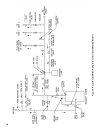
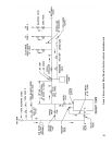
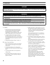
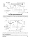
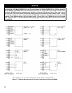
3. Wiring should conform to Figure 13 and/or 14.
B. System Controls and Wiring
1. Refer to National Electric Code or Local Electric
Codes for proper size and type of wire required.
Follow Code.
2. Use anti-short bushings on all wiring passing
through boiler jacket, junction boxes and/or control
boxes.
3. Use armored cable (BX) over all exposed line
voltage wiring.
4. If an Alliance indirect water heater is used, use
priority zoning. Do not use priority zoning for
Hydro-Air Systems.
5. Single Zone System – Refer to Figure 13 or 14 of
this manual for the electrical diagram for this type
of system. Connect the system circulator wire leads
to the proper locations on the Aquastat control,
L7224C/L7248C.
Connect the thermostat to the ‘T-T’ terminals on
the L7224C/L7248C control. Set thermostat heat
anticipator settings to 0.60 amps.
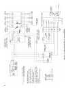
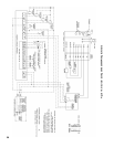
6. Conventional Circulator Zoned System – Refer to
Figure 15 for the electrical diagram for this type of
system.
Read, understand and follow all of the instructions
provided with the Honeywell R8888 control.
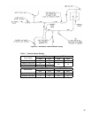
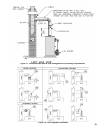
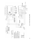
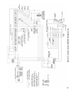
7. Conventional Zone Valve Zoned System – Refer
to Figure 16. Wiring to the most popular models of
zone valves are given in Figure 17.
Locate C1 and C2 inside the L7224C Honeywell
control. Connect the two (2) terminals to the system
circulator wire leads, supplied with boiler.
Connect the H1 and H2 terminals inside the R8889
to the ‘T-T’ terminals in the L7224C Honeywell
Control. Refer to Figure 16.
Connect the thermostat of each zone and the
circulator for that zone to R8889 panel. If an
Alliance indirect water heater is used, connect the
Alliance thermostat and circulator to the Zone 1
terminals of the R8889. Set thermostat anticipator
settings to 0.12 amps.
V. Electrical
DANGER
Positively assure all electrical connections are unpowered before attempting installation or service of
electrical components or connections of the boiler or building. Lock out all electrical boxes with padlock
once power is turned off.
WARNING
Failure to properly wire electrical connections to the boiler may result in serious physical harm.
Electrical power may be from more than one source. Make sure all power is off before attempting any
electrical work.
Each boiler must be protected with a properly sized fused disconnect.
Never jump out or make inoperative any safety or operating controls.
The wiring diagrams contained in this manual are for reference purposes only. Refer to the wiring diagram
of any controls used with the boiler. Read, understand and follow all wiring instructions supplied with
the controls.