13
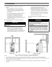
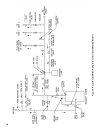
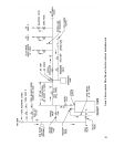
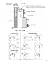
and return line as illustrated in Figures 8 and 9
in order to regulate water ow for maintenance
of higher boiler water temperature. Set the
bypass and return valves to a half throttle
position to start. Operate boiler until the system
water temperature reaches its normal operating
range. Adjust the valves to maintain 180°F to
200°F boiler water temperature and greater the
120°F return temperature. Adjust both valves
simultaneously. Closing the boiler return valve
while opening the bypass valve will raise the
boiler return temperature. Opening the boiler
return valve while closing the by-pass valve will
lower the boiler return temperature.
e. A water boiler installed above radiation level
must be provided with a low water cutoff device
as part of the installation.
If a low water cut-off is required, it must be
mounted in the system piping above the boiler.
The minimum safe water level of a hot water
boiler is just above the highest water containing
cavity of the boiler; that is, a hot water boiler
must be full of water to operate safely.
B. Install Safety Relief Valve. See Figures 8 and 9.
Safety Relief Valve must be installed with spindle in
the vertical position. Installation of the relief valve
must be consistent with ANSI/ASME Boiler and
Pressure Vessel Code, Section IV.
WARNING
Safety (relief) valve discharge piping must be
piped near oor to eliminate potential of severe
burns. Do not pipe in any area where freezing
could occur. Do not install any shut-off valves,
plugs or caps.
C. Install Drain Valve in return piping. See Figures 8 and
9.
D. Oil, grease, and other foreign materials which
accumulate in new hot water and a new or reworked
system should be boiled out, and then thoroughly
ushed. A qualied water treatment chemical specialist
should be consulted for recommendations regarding
appropriate chemical compounds and concentrations
which are compatible with local environmental
regulations.
E. After the boiler and system have been cleaned and
ushed, and before relling the entire system add
appropriate water treatment chemicals, if necessary, to
bring the pH between 7 and 11.
WARNING
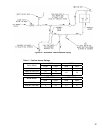
Installation is not complete unless a safety relief valve is installed as shown in Figure 1 or 1A.


