


5
II. Installation Instructions
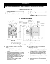
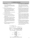
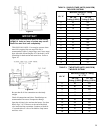
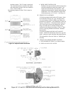
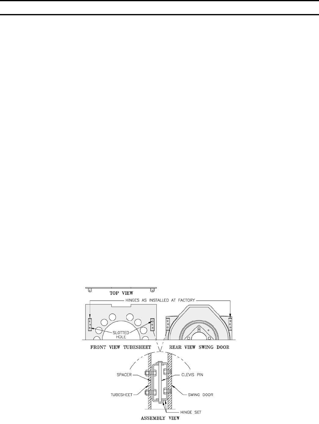
Figure 3: Hinge Installation & Assembly, LE Boiler
1. REMOVE CRATE
A. Remove all fasteners at crate skid.
B. Lift outside container and remove all other inside
protective spacers and bracing. Remove container
containing Safety Relief Valve, Boiler Drain Valve
and Pipe Fittings.
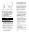
2. REMOVAL OF BOILER FROM SKID
A. Tilt boiler, "walk" boiler backward, and set rear legs
down on oor. Tilt boiler backward, pull skid
forward and set front legs down on edge of skid.
Install close coupling, tee, and plug in return
coupling, see Step 7 and Figure 1. Point tee toward
permanent return location.
B. Tilt boiler backward and remove skid. Be careful not
to damage Burner and Jacket.
3. CHANGE HINGE POSITION if necessary.
A. Look at the area where boiler will be installed. If
left side of boiler will be less than 12 inches from a
wall, move hinges to right side of boiler. See B
through I below.
B. Pull 2 halves of Burner Swing Door Interlock apart.
Swing Door Interlock is connected to T-T terminals
on R7184A Control. Lift Honeywell R7184A
Control off of Burner Junction Box, open Burner
Ignition Transformer and disconnect wiring harness
from left side of burner. Find round plastic cover
inside Junction Box and install in hole in left side
of burner.
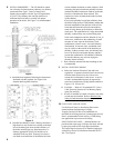
C. Remove 8 sheet metal screws from jacket. Remove
rear jacket box and bend both sides of Jacket
Wrapper up, see Figure 19.
D. Remove 2 (two) 5/16" - 18 x 3" long hex head cap
screws and atwashers from right side of door.
Remove 2 hairpin cotter pins and 2 hinge pins from
hinges on left side of door and remove Door
Assembly from boiler. Inspect Front and Rear
Door Insulation Pieces and Combustion Chamber
Liner, see Step 6.
E. Remove 4 hex nuts from bolts that attach hinges and
hinge spacers to left side of Tubesheet. Remove 4
hex head cap screws that attach hinges to door.
F. Attach 2 hinge brackets & spacers to Tubesheet and
2 hinge brackets to Door on right side of boiler. 3
Holes in each Hinge Bracket must line up with 3
matching holes in Spacer, Tubesheet or Door. See
Figure 3. Tighten hex nuts, bolts and screws by
hand only.
G. Replace door assembly. Hinge brackets attached to
door must rest on top of hinge brackets attached to
tubesheet. See Figure 3. Slide hinge pins through
hinges from top and install cotter pins. Close door
and install 5/16" - 18 x 3" long hex head cap screws
through atwashers and left side of door and into
tapped holes in tubesheet. Tighten all hex nuts,
bolts and screws. When door is installed properly,
it is parallel to Tubesheet when viewed from top
and sides.
H. Bend sides of Jacket Wrapper down and attach 2
Jacket Straps to 4 slots at bottom of Jacket Wrapper
sides with sheet metal screws. Install Rear Jacket
Box with 4 sheet metal screws. See Figure 19.
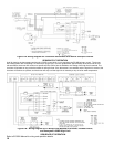
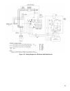
I. Connect wiring harness to a knockout on right side
of Junction Box and install Honeywell R7184A
Control, see Wiring Diagram, Figures 11A and 11B.
Reconnect Swing Door Interlock.