


15
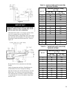
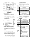
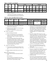
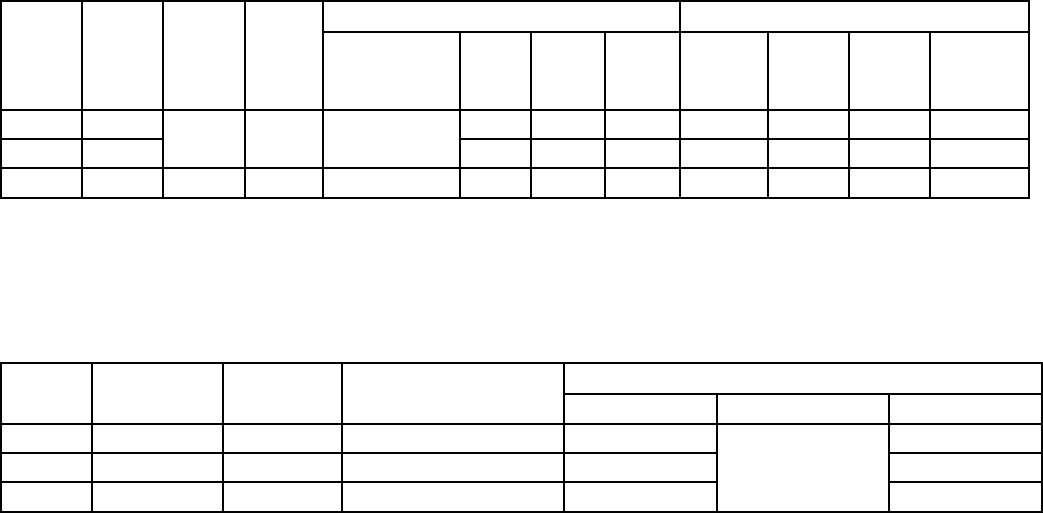
TABLE 6: BECKETT AFG BURNER
C. Attach a plastic hose to fuel pump vent tting and
provide a pan to catch the oil.
D. REMOVE GAUGE PORT PLUG from fuel pump
and install pressure gauge.
E. REMOVE FLAME PLUG IN SWING DOOR.
8. START OIL BURNER
A. Open vent tting on fuel pump.
B. TURN ‘ON’ BURNER service switch and allow
burner to run until oil ows from vent tting in a
SOLID stream without air bubbles for approximate-
ly 10 seconds.
C. Close vent tting and burner ame should start
immediately after pre-purge is complete. Pre-purge
prevents burner ame until 10 seconds has elapsed
after initial power is applied to burner. During pre-
purge, the motor and ignitor will operate but the oil
valve will remain closed. Refer to Oil Primary
Control Instructions for more details.
9. ADJUST OIL PRESSURE
A. Locate oil pressure adjusting screw and turn screw
to obtain the oil pressure indicated in Tables 6 and
6A.
B. DO NOT REMOVE PRESSURE GAUGE until
later.
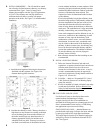
10. OTHER ADJUSTMENTS
A. ADJUST THE AIR BAND AND/OR AIR SHUT-
TER
Beckett Burners:
Adjust air supply by loosening lock screws and
moving the air shutter and if necessary the air band.
Refer to Table 6 for preliminary settings.
B. ADJUST DRAFT REGULATOR for a draft of 0 to
maximum of -.03" (water gauge) in the breeching
after chimney has reached operating temperature
and while burner is running. Burner will operate
with a positive draft over re and zero draft in the
breeching. Adjust Draft Regulator such that
maximum draft of -.03" is reached in coldest
weather.
C. READJUST AIR BANDS on burner for a light
orange colored ame. Use a smoke tester and adjust
air for minimum smoke (not to exceed #1) with a
minimum of excess air. Make nal check using
suitable instrumentation to obtain a CO
2
of 11.5 to
12.5%. These settings will assure a safe and
efcient operating condition. If the ame appears
stringy instead of a solid re, try another nozzle of
the same type. Flame should be solid and compact.
After all adjustments are made recheck for a draft
of zero to -.03" (water gauge) in breeching.
D. TURN “OFF” BURNER and remove pressure
gauge. Install gauge port plug and tighten. Start
burner again.
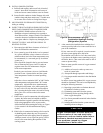
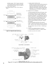
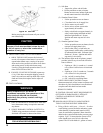
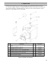
E. CAD CELL LOCATION AND SERVICE
The burner is supplied with a cadmium sulde ame
detector mounted at the factory, mounted on the
bottom of the transformer. See Figure 16. To
service cad cell or to replace the plug in portion,
swing open the transformer. After service is
complete, be sure to fasten down the transformer.
F. FLAME FAILURE
The LE boiler controls operate the burner automati
-
cally. If for unknown reasons the burner ceases to
re and the reset button on the primary control has
tripped, the burner has experienced ignition failure.
Boiler
Model
Firing Rate
(GPH)
Burner
Model
Nozzle
Settings
Air Gate Pump Pressure Turbulator
LE1 0.60 F3 Delavan 0.50 x 60°A 2.8
145
0.5
LE2 1.00 F5 Delavan 0.85 x 60°A 3.0 1.0
LE3 1.25 F5 Delavan 1.00 x 60°A 3.5 3.0
TABLE 6A: RIELLO BURNER SPECIFICATIONS
Boiler
Model
Firing
Rate
(GPH)
Head
Static
Disc
Nozzle Settings
Manufacturer GPH Angle Type
Air
Shutter
Air
Band
Head
Pump
Pressure
(PSIG)
LE1 0.60 *
MB(L1) 3-3/8U
Hago or
Delavan
0.50 70° B 5 0 N/A 140
LE2 1.00 0.85 60° B 10 0 N/A 140
LE3 1.25 + MD(V1) 2-3/4U Delavan 1.10 45° B 10 1.5 0 140
Settings are approximate and must be veried by Smoke and Carbon Dioxide measurement. Readjust where necessary.
See Text of the Manual.
* Install low ring rate bafe for 0.60 GPH ring rate.
+ Do not change the ring rate of the 1.25 GPH burner.