


16
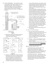
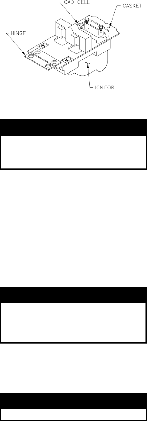
Figure 16: Cad Cell
Before pressing the reset button call your service-
man immediately.
NOITUAC
nehwrenrubehttratsottpmettatonoD
tinuehtnehw,detalumuccasahliossecxe
noitsubmocehtnehwro,ropavfollufsi
.tohyrevsirebmahc
11. CHECK FOR CLEAN CUT OFF OF BURNER
A. AIR IN THE OIL LINE between fuel unit and
nozzle will compress when burner is on and will
expand when burner stops, causing oil to squirt
from nozzle at low pressure as burner slows down
and causing nozzle to drip after burner stops.
Usually cycling the burner operation about 5 to 10
times will rid oil line of this air.
B. IF NOZZLE CONTINUES TO DRIP, repeat step
(11A). If this does not stop the dripping, remove
cutoff valve and seat, and wipe both with a clean
cloth until clean, then replace and re-adjust oil
pressure.
12. TEST CONTROLS.
GNINRAW
sireliobehtfonoitallatsnierofeB
ehtfonoitarepoeht,etelpmocderedisnoc
,dekcehcebdluohsslortnocreliob
hgihdnalortnocyramirpehtylralucitrap
.lortnoctimil
A. CHECK THERMOSTAT OPERATION. Raise and
lower thermostat setting as required to start and
stop burner.
B. VERIFY PRIMARY CONTROL SAFETY FEA-
TURES using procedures outlined in instructions
furnished with control or instructions below:
NOITUAC
YLNONAMECIVRESGNITAEHROF
(1) Safe Start
i. Jumper the yellow cad cell leads.
ii. Follow procedure to turn on burner.
Burner must not start, indictor light turns
on and control remains in Idle Mode.
(2) Simulate Flame Failure.
i. Follow procedure to turn on burner.
ii. Close hand valve in oil supply line.
iii. Device enters recycle mode.
iv. Device tries to restart system after
approximately 60 seconds.
v. Safety switch locks out approximately in
safety switch timing indicated on label.
Indicator light ashes at 1 Hz rate.
Ignition and motor stop and oil valve
closes.
(3) Simulate Ignition Failure.
i. Follow procedure to turn on burner, but do
not open oil supply hand valve.
ii. Observe that safety switch locks out
approximately within safety switch timing
as indicated on the label. Indicator light
ashes at 1 Hz rate. Ignition and motor
stop and oil valve closes.
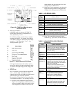
(4) The indicator light on the oil primary control
provides lockout, recycle and cad cell indica-
tions as follows:
i. Flashing at 1 Hz (½ second on, ½ second
off): system is locked out or in restricted
mode.
ii. Flashing at ¼ Hz (2 seconds on, 2 seconds
off): control is in recycle mode.
iii. On: cad cell is sensing ame.
iv. Off: cad cell is not sensing ame.
C. CHECK HIGH LIMIT CONTROL. Jumper
thermostat terminals. Allow burner to operate until
shut-down by limit. Installation is not considered
complete until this check has been made.
REMOVE JUMPER.
IF CONTROLS DO NOT MEET REQUIREMENTS
OUTLINED IN PARAGRAPH 12, REPLACE
CONTROL AND REPEAT CHECK-OUT
PROCEDURES.
13. BOILER AND SYSTEM CLEANING INSTRUC-
TIONS FOR TROUBLE FREE OPERATION
A. Filling of Boiler and System — General —-In a hot
water heating system, the boiler and entire system
(other than the expansion tank) must be full of
water for satisfactory operation. Water should be
added to the system until the boiler pressure gauge
registers 12 psi. To insure that the system is full,
water should come out of all air vents when
opened. The LE boiler holds 6.1 gallons of water.