


12
III. Operating and Service Instructions
1. ALWAYS INSPECT INSTALLATION BEFORE
STARTING BURNER.
2. FILL HEATING SYSTEM WITH WATER.
NOTE: It is important to properly remove the oil and
dirt from the system.
CLEAN HEATING SYSTEM If boiler water is dirty,
refer to step 13 for proper cleaning instructions.
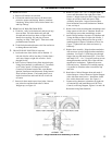
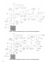
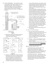
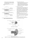
A. Fill entire Heating System with water and vent air
from system. Use the following procedure on a
Series Loop or Multi-Zoned System installed as per
Figures 4 and 5, to remove air from system when
lling:
(1) Close isolation valve in boiler supply piping.
(2) Isolate all circuits by closing zone valves or
balancing valves.
(3) Attach a hose to hose bib located just below
isolation valve in boiler supply piping.
(Note - Terminate hose in ve gallon bucket at a
suitable oor drain or outdoor area).
(4) Starting with one circuit, open zone valve.
(5) Open hose bib.
(6) Open ll valve (Make-up water line should be
located directly above isolation valve in boiler
supply piping).
(7) Allow water to overow from bucket until dis
charge from hose is bubble free for 30 seconds.
(8) Open zone valve to the second zone to be
purged, then close the rst. Repeat this step
until all zones have been purged, but always
have one zone open. At completion, open all
zone valves.
(9) Close hose bib, continue lling the system until
the pressure gauge reads 12 psi. Close ll
valve.
(Note - If make-up water line is equipped with
pressure reducing valve, system will automati-
cally ll to 12 psi. Leave globe valve open).
(10) Open isolation valve in boiler supply piping.
(11) Remove hose from hose bib.
3. CHECK CONTROLS, WIRING AND BURNER to be
sure that all connections are tight and burner is rigid,
that all electrical connections have been completed and
fuses installed, and that oil tank is lled and oil lines
have been tested.
4. LUBRICATION — Follow instruction on burner and
circulator label to lubricate, if oil lubricated. Most
motors currently used on residential type burners
employ permanently lubricated bearings and thus do
not require any eld lubrication. Water lubricated
circulators do not need eld lubrication.
Do not over-lubricate. This can cause as much trouble as no
lubrication at all.
5. ADJUST CONTROLS SETTINGS with burner service
switch turned “ON”.
A. SET ROOM THERMOSTAT about 10° above
room temperature.
B. PRESS RED RESET BUTTON.
C. On WATER BOILERS WITHOUT TANKLESS
HEATERS equipped with L7248 electronic
aquastat controller, set High Limit (HL) at 180°F.
This temperature can be varied to suit installation
requirements. L7248 controller has the High Limit
adjustment range from 180°F to 240°F (82°C to
116°C). High Limit Differential is xed at 15°F
(8°C).
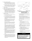
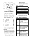
D. ADJUSTING AQUASTAT CONTROLLER
SETTINGS. To discourage unauthorized changing
of Aquastat settings, a procedure to enter the
ADJUSTMENT mode is required. To enter the
ADJUSTMENT mode, press the UP, DOWN, and
I buttons (refer to Figure 12) simultaneously for
three seconds. Press the I button until the feature
requiring adjustment is displayed:
• HL_ High Limit.
• °F °C.
Then, press the UP and/or DOWN buttons to move
the set point to the desired value. After 60 seconds
without any button inputs, the control will auto-
matically return to the RUN mode.
L7248 Aquastat Controller will not display Low
Limit and Low Limit Differential adjustment
features.
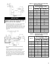
GNINRAW
erevesesuacnachcihwdrazahlaitnetopaevahroodgniwsrenrubhtiwdeppiuqesreliobllA
ffonrut,roodgniwsgninepoerofeB.derongifiefilfossolroyrujnilanosrep,egamadytreporp
gniriwkcolretnIrooDgniwSrenruBfosevlahowttcennocsiddnareliobothctiwsecivres
oteruseB.rebmahcnoitsubmocehtedistuorenrubfogniriflatnediccatneverpotssenrah
rooDgniwSrenruBfosevlahowttcennocerdnayletelpmocrenetsafroodgniwsnethgit
.detelpmocsiecivresnehwkcolretnI