


9
III. Water Piping and Trim
A. Design and install boiler and system piping to
prevent oxygen contamination of boiler water.
There are many possible causes of oxygen
contamination such as:
1. Addition of excessive make-up water as a result of
system leaks.
2. Absorption through open tanks and fittings.
3. Oxygen permeable materials in the distribution
system.
In order to insure long product life, oxygen sources
should be eliminated. This can be accomplished by
taking the following measures:
1. Repairing system leaks to eliminate the need for
addition of make-up water.
2. Eliminating open tanks from the system.
3. Eliminating and/or repairing fittings which allow
oxygen absorption.
4. Use of non-permeable materials in the distribution
system.
5. Isolating the boiler from the system water by
installing a heat exchanger.
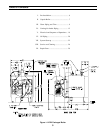
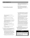
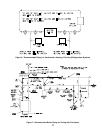
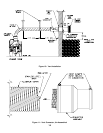
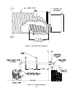
B. Connect System supply and return piping to boiler. See
Figures 5 and 7. Also consult I=B=R Installation and
Piping Guides. Maintain minimum ½ inch clearance from
hot water piping to combustible materials.
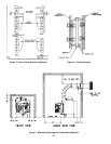
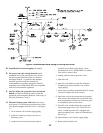
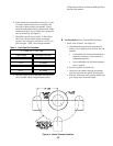
1. If this boiler is used in connection with refrigeration
systems, the boiler must be installed so that the
chilled medium is piped in parallel with the heating
boiler using appropriate valves to prevent the chilled
medium from entering the boiler, see Figure 6. Also
consult I=B=R Installation and Piping Guides.
2. If this boiler is connected to heating coils located in
air handling units where they may be exposed to
refrigerated air, the boiler piping must be equipped
with flow control valves to prevent gravity
circulation of boiler water during the operation of the
cooling system.
3. If boiler is used with an Alliance Indirect-Fired
Domestic Water Heater, install the Alliance as a
separate heating zone. Refer to the Alliance
Installation, Operating, and Service Instructions for
additional information.
4. Use a system bypass if the boiler is to be operated in
a system which has a large volume or excessive
radiation where low boiler water temperatures may
be encountered (i.e. converted gravity circulation
system, etc.).
The bypass should be the same size as the supply
and return lines with valves located in the bypass
and return line as illustrated in Figures 5 and 7 in
order to regulate water flow for maintenance of
higher boiler water temperature.
Set the by-pass and return valves to a half throttle
position to start. Operate boiler until the system
water temperature reaches its normal operating
range.
Adjust the valves to maintain 180°F to 200°F boiler
water temperature and greater than 120°F return
temperature. Adjust both valves simultaneously.
Closing the boiler return valve while opening the by-
pass valve will raise the boiler return temperature.
Opening the boiler return valve while closing the by-
pass valve will lower the boiler return temperature.
5. A hot water boiler installed above radiation level
must be provided with a low water cutoff device as
part of the installation.
C. Install Safety Relief Valve. See Figures 5 and 7. Safety
Relief Valve must be installed with spindle in vertical
position. Installation of the relief valve must be
consistent with the ANSI/ASME Boiler and Pressure
Vessel Code, Section IV.
WARNING
Safety (relief) valve discharge piping must
be piped near floor to eliminate potential of
severe burns. Do not pipe in any area where
freezing could occur. Do not install any shut-
off valves, plugs or caps.