


12
IV. Venting / Air Intake Piping
A. General Guidelines
1. Vent system installation must be in accordance with
these instructions and applicable provisions of local
building codes. Contact local building or fire officials
about restrictions and installation inspection in your
area.
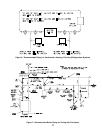
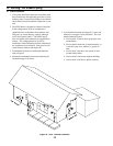
2. The LEDV Series is designed as a Direct Vent boiler.
In this configuration, all air for combustion is
supplied directly to the burner from outdoors and
flue gases are vented directly outdoors (through
wall). See Figures 10 and 11. The LEDV may be
side-wall vented with combustion air supplied from
indoors. This configuration may be used in
installations where infiltration provides adequate air
for combustion and ventilation. Flue gases are still
vented directly outdoors (through wall).
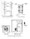
3. For minimum clearances to combustible materials
refer to Figure 2.
4. Maximum wall thickness that vent terminal may be
installed through is 10 inches.
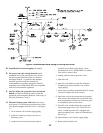
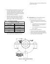
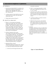
5. Vent Terminal Location (see Figure 8). Locate vent
terminal so vent pipe is short and direct. The vent
terminal must be located:
a. Not less than 12 inches above grade plus snow
accumulation.
b. Not less than 4 feet below, 4 feet horizontally, or
1 foot above any door, window, or gravity air
inlet.
c. Not less than 3 feet above any forced air inlet
located within 10 feet.
d. Not less than 2 feet from an adjacent building.
e. Not less than 7 feet above a public walkway.
Figure 8: Vent Terminal Location