


22
VII. System Start-up
A. ALWAYS INSPECT INSTALLATION BEFORE
STARTING BURNER.
B. FILL HEATING SYSTEM WITH WATER. Refer to
Section III, G.
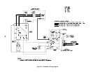
C. CHECK CONTROLS, WIRING AND BURNER to be
sure that all connections are tight and burner is rigid,
that all electrical connections have been completed and
fuses installed, and that oil tank is filled and oil lines
have been tested.
D. LUBRICATION — Follow instruction on burner and
circulator label to lubricate, if oil lubricated. Most
motors currently used on residential type burners
employ permanently lubricated bearings and thus do
not require any field lubrication. Water lubricated
circulators do not need field lubrication.
Do not over-lubricate. This can cause as much trouble
as no lubrication at all.
E. SET CONTROLS with burner service switch turned
“OFF”.
1. SET ROOM THERMOSTAT about 10° above
room temperature.
2. PRESS RED RESET BUTTON on R8184P Oil
Primary Control and release.
3. Set high limit dial on L8148 at temperature to suit
requirements of installation.
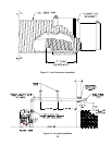
F. BURNER START-UP
1. VERIFY burner settings.
a. Refer to Table 4.
2. Open all shut-off valves in the oil supply line to the
burner.
3. Attach a plastic hose to fuel pump vent fitting and
provide a container to catch the oil.
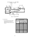
4. REMOVE GAUGE PORT PLUG from fuel pump
and install pressure gauge.
5. REMOVE TEST PLUG IN FLUE COLLAR.
6. Close the service switch to start the burner. If the
burner does not start immediately, check the
manual overload switch on the motor, if so
equipped, and the safety switch of the burner
primary control.
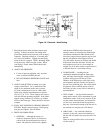
WARNING
All boilers equipped with burner swing door have a potential hazard which can cause severe
property damage, personal injury or loss of life if ignored. Before opening swing door, turn off
service switch to boiler to prevent accidental firing of burner outside the combustion chamber.
Be sure to tighten swing door fastener completely when service is completed.
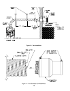
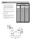
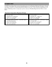
TABLE 4: BECKETT AFII BURNER
Boiler
Model
Firing Rate
(GPH)
Burner
Air Tube
Combination
Delavan Nozzle
Settings
Air Head
(stop screw)
Pump Pressure
(PSIG)
LEDV-1 0.60 AFII 85 HLX50HD 0.50 x 70°B 2.5 #2 140
LEDV-2 1.00 AFII 150 HLX50HE 0.85 x 60°B 3.5 #3 140
LEDV-3 1.25 AFII 150 HLX50HE 1.00 x 60°B 4.0 #5 140