


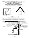
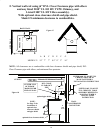


SECTION VI
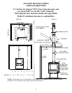
ALCOVE INSTALLATION
AND CLEARANCES
Select an installation location that will give the best airflow from the front of the
heater to the remainder of the home.
PREPARING THE STOVE FOR INSTALLATION
1. Inspect the unit for any obvious physical damage.
2. Plug the power cord into a 115V AC outlet to test the motor and fan when optional motor is
being used. “Do not run power cord under unit or in high traffic areas”.
3. Check the primary air draft control to ensure that it slides freely.
4. Remove any items from within the firebox. Spread a dropcloth on the floor behind the
heater. Next, tilt the heater so that the back is on the drop cloth.
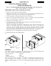
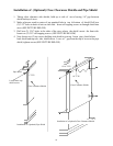
5. If leg kit is to be used follow steps 1-6.
6. Then obtain four legs, attach the legs to holes in bottom of unit with bolts and washers
supplied with the leg kit. (See Figure 20.)
7.
Open the corresponding freestanding kit and obtain the stand. Place the stand against the
bottom of the heater (angle side to heater).Center stand front to rear ,and also
center the stand left and right ,and mark screw locations on bottom of the stove through
outer holes of stand mounting angles. Set stand aside and drill four 7/32" holes in heater
bottom.Then mount stand to bottom of heater with screws provided. (See Figure 21).
8. Obtain four (4) 3/16" self-tapping screws and secure the stand to the heater.
9. Reposition the heater to the upright position.
10.
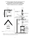
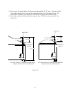
Chimney
This model is designed for connection to the following listed 2100º UL103 HT chimneys and
parts. Follow chimneys manufacturer's instructions carefully.
Simpson Duravent Metal Fab
Security Airjet
Selkirk Metal Bestos Jakes Evans
This room heater must be converted to (1) a chimney complying with the requirements for
Type HT chimneys in the Standard for chimneys, Factory-Built, Residential, Type and
Building Heating Appliance, UL 103, or (2) a code approved masonry chimney with a flue
liner.
Figure 20
Figure 21
29