


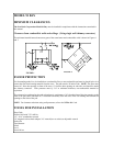
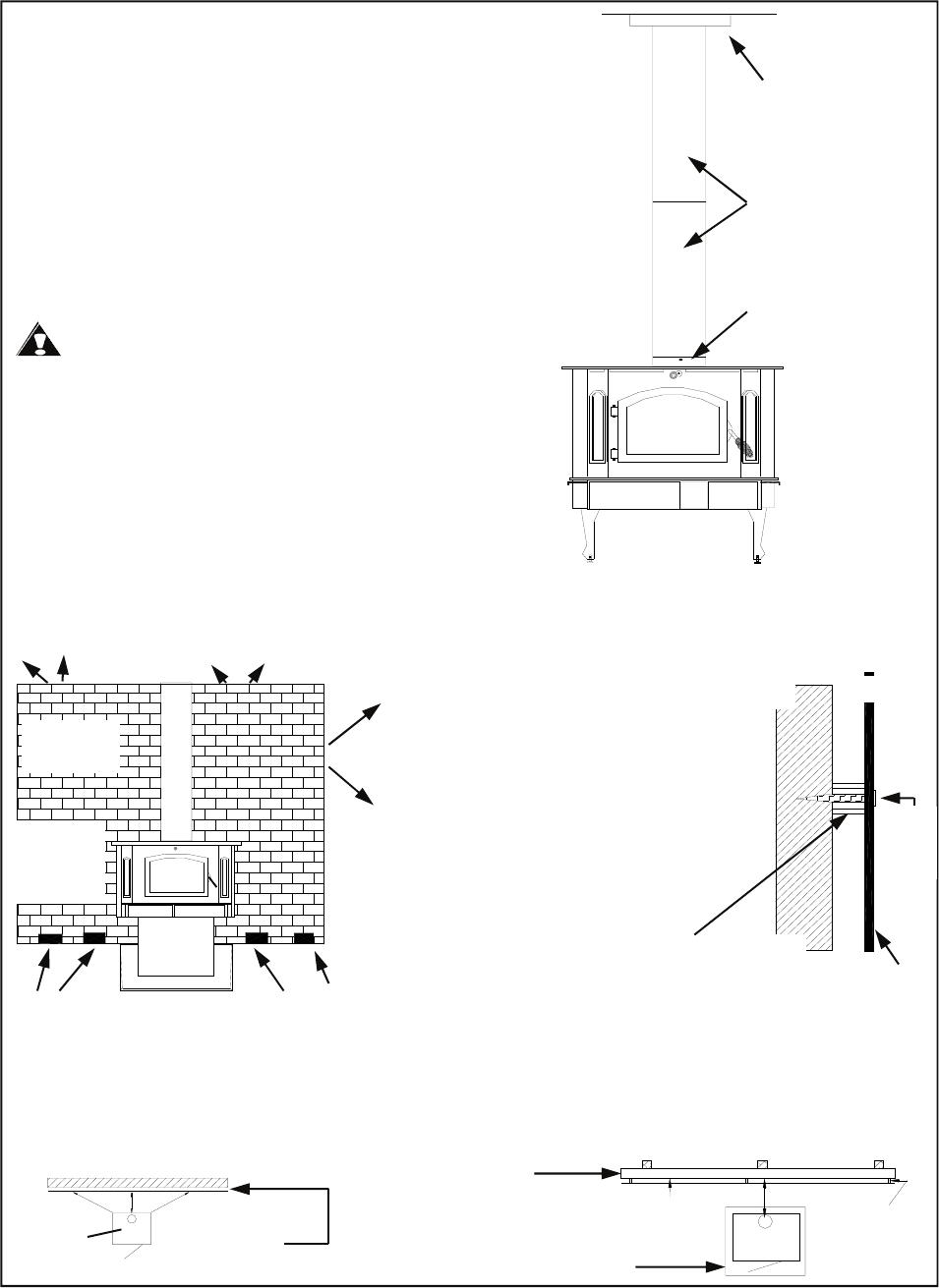
Example: The rear clearance for the Model 91 from page 12 is 18". (See Figure 1.) This clearance may be reduced
by 50% to 9" by using either of the wall protection devices mentioned below.
ALTERNATIVES FOR WALL PROTECTION
Ceiling Exit - Close Clearance
1. Suspend a plumb bob from the ceiling above the
unit so that the weight is hanging in the center of
the flue exit. (A small weight on a string will
serve as a plumb bob.) Mark the ceiling where
the string is suspended to locate the center of the
chimney hole.
2. After locating the center of the hole, install the
ceiling support box, chimney, flashing, and rain.
3. Install Double Wall Connector and chimney
system per manufacturer’s written operating
instructions. See manufacturer’s list of tested
pipes.
CAUTION: Because of the high efficiency and
low flue gas temperature, freestanding catalytic
heaters connected to masonry chimneys with
oversized flue liners may encounter drafting problems
A positive flue liner (optional) may be necessary to
help draft. A poor drafting chimney may result in poor
performance from the Model 91. This is not a defect
of the Model 91 but a defect in the chimney. This is
not a warranty problem with the Model 91. Contact
dealer for possible solutions for chimney.
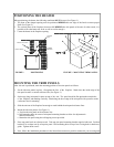
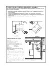
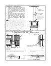
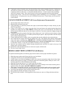
FIGURE 8
CEILING
SUPPORT BOX
SINGLE WALL
PIPE
BRICK CLEAR-
ANCE REDUC-
TION SYSTEM
BRICK WALL
SPACED OUT I
INCH FROM
PROTECTED
SURFACE
LEAVE I INCH
CLEARANCE FOR
AIR CIRCULATION
AIR CIRCULATION
FLOOR
BRICK WALLS MAY BE ATTACHED TO COMBUSTIBLE WALLS USING WALL TIES
IF BRICK IS USED. BE SURE FLOOR CAN WITHSTAND WEIGHT OF BRICK.
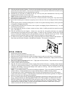
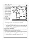
COMBUSTIBLE WALL
WOOD STOVE
CLEARANCE REDUC-
TION STEM SPACED
OUT 1 INCH
COMBUSTIBLE WALL
AIR SPACE
1"
NAIL OR
SCREW
ANCHOR
MINIMUM
24 GAUGE
SHEET
METAL
1 INCH NON-COMBUSTIBLE SPACER SUCH AS
STACKED WASHERS, SMALL DIAMETER PIPE, TUBING
OR ELECTRICAL CONDUIT.
DO NOT USE FASTENERS DIRECTLY BEHIND CHIMNEY
CONNECTOR OR STOVE.
TOP VIEW
COMBUSTIBLE WALL
MINIMUM 24 GAUGE
SHEET METAL
NON-COMBUSTIBLE
SPACERS
FLOOR PROTECTOR
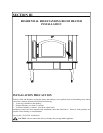
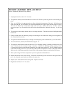
FIGURE 9
OPTIONAL NBC
CAST CHIMNEY
CONNECTOR
(COLLAR)