


PREPARING THE STOVE FOR INSTALLATION
1. Inspect the unit for any obvious physical damage.
2. Plug the power cord into a 115V AC outlet. Set switch to “Manual” and rheostat to “High” position to ensure
motor operates properly. You cannot check the motor when the switch is in the “Off” or “Automatic”
position, unless a heat gun is used to heat the internal thermostat.
3. Check the primary air draft controls to ensure that they operate freely.
4. Check the operation of the bypass damper control to ensure that it will open and close properly.
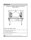
5. To attach legs, remove any items within firebox. Spread drop cloth on the floor behind the heater. Tilt the
heater so that back is on the drop cloth. Attach legs to pre-drilled holes in bottom of heater. If using optional
pedestal, mounting holes will need to be drilled.
6. Reposition the heater to the upright position.
CHIMNEY
Ceiling Exits:
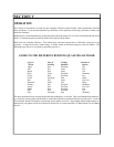
The Model 91 Bay is designed for connection to: 1)
Simpson Dura-Vent, 2) Security, 3) Selkirk Metal
Bestos, 4) Metal Fab, 5) Air Jet, listed as 2100
o
pipe and
parts.
“Follow chimney and chimney connector manufacturers
instructions and local building codes for installation
through combustible walls or ceilings.” This heater can
only be installed freestanding by using one of the
following requirements: 1) must use a brand of chimney
pipe, as listed above, complying to the requirements for
Type HT chimneys in the standard code for chimneys,
Factory-Built, Residential Type and Building Heating
Appliance, UL 103 or 2) a code approved masonry
chimney with a flue liner.
CAUTION: Certain installation types require the use of
certain chimney types. Please follow these instructions
exactly.
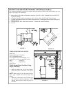
DETERMINING THE CHIMNEY
LOCATION
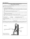
A. Ceiling Exit (Using Single Wall Pipe and UL 103
HT type chimney system listed with manufactur-
er in this section of manual)
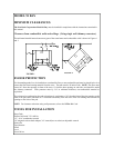
1. Suspend a plumb bob from the ceiling above
the unit so that the weight is hanging in the
center of the flue exit. (A small weight on a
string will serve as a plumb bob.) Mark the ceiling where the string is suspended to locate the center of
the chimney.
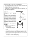
2. After locating the center of the hole, install the ceiling support box, chimney, flashing, and rain cap per
the chimney manufacturer’s instructions.
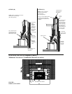
3. Connect the stove to the ceiling support box by using #24 ga. minimum blued or black steel chimney
pipe. (DO NOT use galvanized pipe.) Each section should fit into the section below or into the opening
on the stove, for drip-free operation. Secure each section together by using at least three (3) sheet metal
screws or rivets.
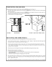
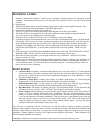
4. You may secure chimney pipe to stove two (2) different ways.
a. With Optional NBC Cast Chimney Connector, See Figure 3.
b. Mounting clips attached to heater and chimney pipe, See Figure 7 on Page 15.
CEILING
SUPPORT BOX
SINGLE WALL
PIPE
FIGURE 3
OPTIONAL NBC
CAST CHIMNEY
CONNECTOR