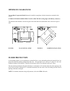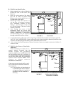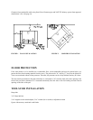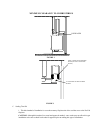
Clearance from combustible walls using listed Close Clearance pipe and 2100
o
HT chimney system from approved
manufacturer’s list. (See page 18)
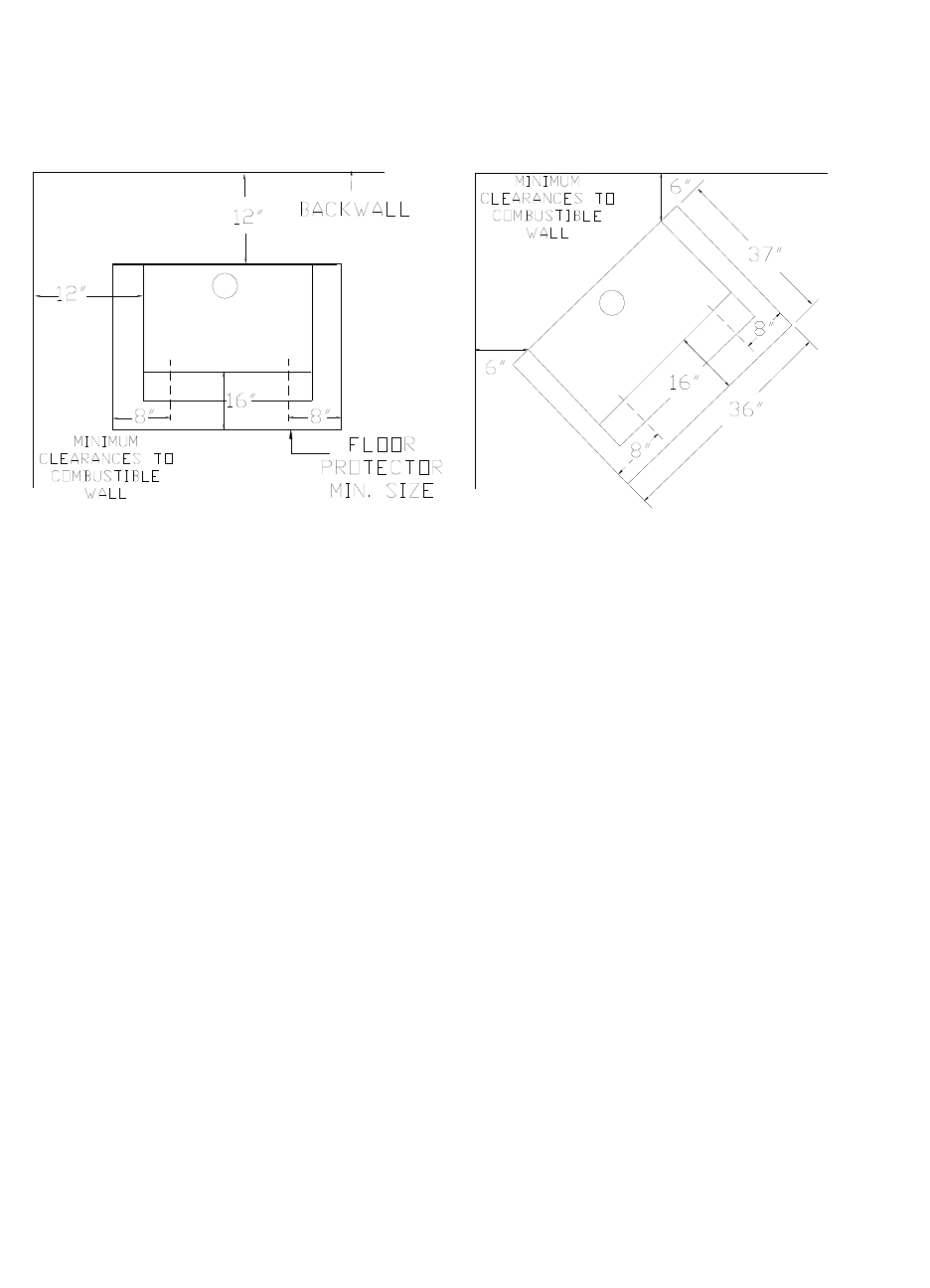
FIGURE 1 WALL INSTALLATION FIGURE 2 CORNER INSTALLATION
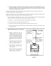
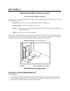
FLOOR PROTECTION
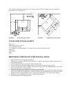
If the room heater is to be installed on a combustible floor, a non-combustible pad must be placed below it to
protect the floor from burning material from the stove. The pad must be 36” wide by 37” deep for the Model 20.
Tests were conducted without a floor protector. Therefore, the protector can be of any thickness and any K* factor.
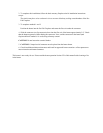
The unit must be positioned on the pad so that there is a minimum of 16” from the front of the door opening to the
front of the pad, and a minimum of 8” measured horizontally from the sides of the fuel loading and ash removal
openings to the sides of the pad.
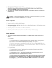
TOOLS FOR INSTALLATION
Drop cloth
3/32” Metal drill bit
5/16” magnetic socket chuck adapter, 5/16” wrench (box or socket) or adjustable wrench
Jigsaw with masonry, metal and wood blades


