


VIII. INSTALL ELECTRICAL ACCESSORIES
A. GENERAL
Refer to the individual instructions packaged with kits or acces-
sories when installing.
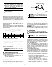
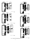
Available electrical accessories include latent capacity control. See
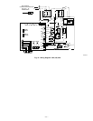
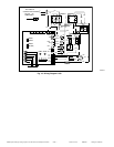
Fig. 11 for typical accessory wiring diagrams.
B. LATENT CAPACITY CONTROL (LCC)
The purpose of an LCC is to provide a dehumidification mode to
assure a 75 percent or less system sensible heat ratio. If indoor unit
installed contains an ECM blower (such as an FK4C or FV4A fan
coil or a 315(A,J)AV or 355MAV gas furnace), no LCC is
required. Indoor products with ECM blowers have enough CFM
range to provide proper airflow for low-speed cooling. If indoor
unit installed has a standard PSC blower motor, the low-speed
airflow available is too great to assure 75 percent or less system
sensible heat ratio. The LCC for standard blower products consists
of a standard humidistat which opens contacts on humidity rise and
a pilot duty relay with 24v coil.
NOTE: If an LCC is desired, low-speed airflow must be main-
tained so that a minimum of 300 CFM/ton can be supplied during
high-speed LCC operation.
LCC OPERATION FOR TYPICAL PSC FAN COILS
The standard blower operation for systems with typical PSC fan
coils is covered in Fig. 11. The blower runs in high speed
regardless if compressor operation is high or low speed. When the
LCC is wired according to Fig. 11 and humidity rises, the
humidistat contacts open and de-energize the relay. If relay is
de-energized, the system operates on high-speed compressor and
high-speed airflow until humidistat closes. Fig. 11 shows the
wiring with a Bryant Thermidistat which controls temperature and
humidity level without the need for an additional humidistat and
relay.
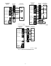
LCC OPERATION FOR TYPICAL PSC FURNACES
The standard blower operation of systems with typical PSC
furnaces is covered in Fig. 11. The blower runs in high or low
speed in conjunction with compressor high- or low-speed opera-
tion. When the LCC is wired according to Fig. 11, humidity rises,
the humidistat contacts open and de-energize the relay. If relay is
de-energized, the system operates on high-speed compressor and
low-speed airflow until humidistat closes. Fig. 11 shows the wiring
with a Bryant Thermidistat which controls temperature and hu-
midity level without the need for an additional humidistat and
relay.
IX. MAKE AIRFLOW SELECTIONS
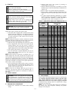
A. AIRFLOW SELECTION FOR 315AAV/355MAV FUR-
NACES
The 315AAV/355MAV Non-Condensing Variable Speed Fur-
naces provide high- and low-speed blower operation to match the
capacities of the compressor at high and low speeds. To select the
recommended airflow and for adjustments to the manual switches
labeled SW1, A/C and CF on the control board refer to the furnace
Installation, Start-Up, and Operating Instructions. The 315AAV
utilizes a control center that allows the installing technician to
select the proper airflows. The A/C switch determines the airflow
during high speed compressor operation. Airflow for hight and low
speed can be calculated at either 350 CFM per ton or 400 CFM per
ton based on the positions of SW1-5.
B. AIRFLOW SELECTION FOR FK4C OR FV4A FAN
COILS
The FK4C and FV4A provides high- and low-speed blower
operation to match the capacities of compressor at high and low
speeds. To select recommended airflow, refer to the FK4C or
FV4A Installation Instructions. The FK4C and FV4A utilize an
EASY SELECT control board that allows the installing technician
to select proper airflows. For adjustments to control board and
recommended A/C SIZE and CFM ADJUST selections, refer to
the fan coil Installation Instructions. This fan coil has an adjustable
blower off delay factory set at 90 sec. for high- and low-speed
blower operation.
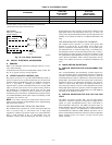
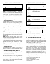
TABLE 2—ACCESSORY USAGE
ACCESSORY
REQUIRED FOR
LONG-LINE
APPLICATIONS
*
(50-175 FT)
REQUIRED FOR
SEACOAST
APPLICATIONS
(WITHIN 2 MILES)
Coastal Filter No Yes
Support Feet No Recommended
Puron® Balance-Port Hard Shutoff TXV Yes† Yes†
* For tubing line sets between 50 and 175 ft horizontal or 20 ft vertical differential refer to Service Manual for Air Conditioners and Heat Pumps Using Puron® Refrigerant.
Crankcase heater and start assist are standard on two-speed units.
† All two-speed units require hard shut-off TXV.
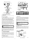
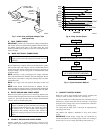
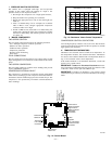
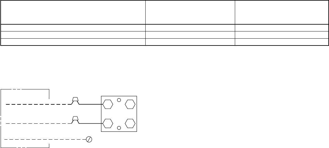
Fig. 10—Line Power Connections
A91306
CONTACTOR
DISCONNECT
PER N. E. C. AND/ OR
LOCAL CODES
FIELD POWER
WIRING
FIELD GROUND
WIRING
GROUND
LUG
—6—