


NOTE: If subcooling charging conditions are not favorable,
charge must be weighed in accordance with unit rating plate ± 0.6
oz/ft of 3/8-in. liquid line above or below 15 ft respectively.
EXAMPLE: To calculate additional charge required for a 25 ft line
set: 25 ft - 15 ft = 10 ft x 0.6 oz/ft=6ozofadditional charge.
XII. SYSTEM FUNCTIONS AND SEQUENCE OF OPERA-
TION
The outdoor unit control system has special functions. The
following is an overview of the two-speed control functions:
A. COOLING OPERATION
This product utilizes a 2-stage cooling indoor thermostat. With a
call for first stage cooling (Yl), the outdoor fan and low capacity
compressor are energized. If low capacity cannot satisfy cooling
demand, high capacity is energized (Yl and Y2 or Y2 only) by the
second stage of indoor thermostat. After second stage is satisfied,
the unit returns to low-speed operation until first stage is satisfied
or until second stage is required again. When both one stage and
two stage cooling are satisfied, the compressor will shut off.
NOTE: If unit has not operated within the past 12 hours or
following a unit power-up, upon the next thermostat high- or
low-speed demand, unit operates for a minimum of 5 minutes in
high speed.
NOTE: When two-speed unit is operating at low speed, system
vapor (suction) pressure will be higher than a standard single-
speed system or high-speed operation. This normal operation is
due to the reduced capacity operating with typically larger indoor
and outdoor coils.
NOTE: Outdoor fan motor will continue to operate for one
minute after compressor shuts off, when outdoor ambient is greater
than or equal to 100°F.
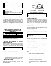
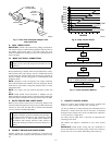
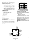
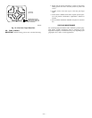
B. STATUS FUNCTION LIGHTS
A system control STATUS function light is located on the outdoor
unit control board (see Fig. 12). The STATUS light provides
signals for several system operations. See Table 5 for codes and
definitions. Table 5 also provides the order of signal importance.
NOTE: Only one code will be displayed on the outdoor unit
control board (the most recent with the highest priority).
C. FACTORY DEFAULTS
Factory defaults have been provided in the event of failure of
outdoor air thermistor, coil thermistor, and/or furnace interface
jumper.
D. ONE MINUTE SPEED CHANGE TIME DELAY
When compressor changes speeds from high to low or low to high,
there is a 1 minute time delay before compressor restarts. The
outdoor fan motor remains running.
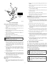
E. COMPRESSOR OPERATION
When the compressor operates in high capacity operation, the
motor rotates clockwise. Both the lower and upper pistons are
eccentric with the rotating crankshaft and both compress refriger-
ant. When the compressor operates in low capacity the motor
reverses direction (rotates counterclockwise). The lower piston
becomes idle and the upper piston compresses refrigerant. The
start and run windings are reversed.
F. CRANKCASE HEATER OPERATION
The two-speed control energizes crankcase heater during unit off
cycle.
G. OUTDOOR FAN MOTOR OPERATION
The outdoor unit control energizes outdoor fan any time compres-
sor is operating. The outdoor fan remains energized during the 1
minute speed change time delay and if a pressure switch or
compressor overload should trip. Outdoor fan motor will continue
to operate for one minute after the compressor shuts off when the
outdoor ambient is greater than or equal to 100°F.
H. COMPRESSOR VOLTAGE FAILURE (6 FLASHES)
The control senses the voltage of the compressor run winding. If
compressor voltage (Vc) is less than 90v when control board is
calling for compressor operation, control shuts compressor off for
15 minutes with outdoor fan running. After 15 minutes (provided
there is a call for Y1 or Y2), control attempts to start compressor.
During this time, a code of 6 flashes appears at control board. If Vc
trip occurs 3 consecutive times during a Y1 request, then low
capacity operation is locked out and control responds to Y2
requests until a reset occurs. If 3 consecutive trips occur in a
combination of Yl and Y2 or all Y2 requests, then both low and
high capacity operation will be locked out. The compressor voltage
failure (6 flashes) can be caused by:
• compressor internal overload trip (refer to Table 6 for correct
winding resistance).
• no 240 volt power supply to outdoor unit.
• failed compressor contactor(s).
• failure of start relay to pick up properly.
• improper wiring.
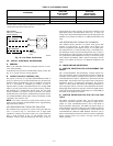
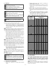
TABLE 4—SUBCOOLING TEMPERATURES
UNIT
TXV TYPE EXPANSION DEVICE
HIGH CAPACITY ONLY
SUBCOOLING AT SERVICE VALVE
024 14°F
036 15°F
048 12°F
060 16°F
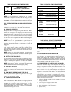
TABLE 5—CONTROL FUNCTION LED CODE
CODE DEFINITION
SIGNAL
IMPORTANCE*
Constant flash
No pause
No demand
Stand by
10
1 flash
w/pause
Low-speed operation 9
2 flashes
w/pause
High-speed operation 8
3 flashes
w/pause
Outdoor thermistor failure 7
4 flashes
w/pause
Outdoor coil thermistor failure 6
3 flashes
pause
4 flashes
Thermistor out of range 5
5 flashes
pause
1 flash
Low pressure switch trip 4
5 flashes
pause
2 flashes
High pressure switch trip 3
6 flashes
w/pause
Compressor V
C
/V
H
trip 2
Constant light
No pause
No flash
Board failure 1
*Function light signal order of importance in case of multiple signal request; 1
is most important.
TABLE 6—DUAL CAPACITY COMPRESSOR
(WINDING RESISTANCE AT 70° ±20°)
WINDING 024 036 048 060
Start (S-C) 2.280 1.850 1.457 0.740
Run (R-C) 0.770 0.745 0.552 0.356
—12—