


I. PRESSURE SWITCH PROTECTION
The outdoor unit is equipped with high- and low-pressure
switches. If the control senses the opening of a high or low
pressure switch, it will respond as follows:
1. De-energize the compressor low or high speed contactor,
2. Keep the outdoor fan operating for 15 minutes,
3. Display the appropriate error code on the status light (see
Table 5).
4. After a 15 minute delay, if Yl or Y2 inputs are on and the
LPS or HPS is reset, energize appropriate compressor
contactor, either low or high.
5. If LPS or HPS has not closed after a 15 minute delay, the
outdoor fan is turned off. If the open switch closes anytime
after the 15 minute delay, then resume operation on call for
Y1 and/or Y2.
J. MAJOR COMPONENTS
TWO-SPEED CONTROL
The two-speed control board controls the following functions:
- Low- and high-compressor contactor operation
- Outdoor fan motor operation
- Crankcase heater operation
- Compressor protection
- Pressure switch monitoring
- Time delays
FIELD CONNECTIONS
The two-speed control received 24vac low-voltage control system
inputs through the screw connections on the left side of the control
board.
TWO-SPEED COMPRESSOR
The two-speed compressor contains motor windings that provide
2-pole (3500 RPM) operation.
COMPRESSOR INTERNAL RELIEF
The compressor is protected by an internal pressure relief (IPR)
which relieves discharge gas into compressor shell when differen-
tial between suction and discharge pressures exceeds 525 psi. The
compressor is also protected by an internal overload attached to
motor windings.
COMPRESSOR CONTROL CONTACTORS
Low and high capacity contactor coils are 24 volts. The electronic
control board controls the operation of the low speed (C-L) and the
high speed (C-H) contactors.
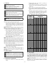
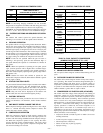
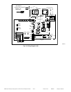
K. TEMPERATURE THERMISTORS
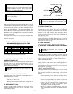
Thermistors are electronic devices which sense temperature. As
the temperature increases, the resistance decreases. Thermistors
are used to sense outdoor ambient and coil temperature. Refer to
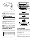
Fig. 13 for resistance values versus temperature.
If the outdoor ambient or coil thermistor should fail, a fault code
appears at two-speed control.
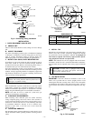
IMPORTANT: Outdoor Air Thermistor Placement Mount out-
door air thermistor underneath unit base pan lip on control box side
of the unit. Attach to base pan with adhesive tape.
IMPORTANT: If outdoor air thermistor is not properly placed
underneath base pan, unit may see nuisance thermistor out of range
faults.
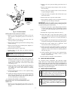
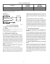
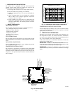
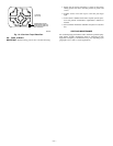
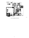
Fig. 12—Control Board
A01192
Defrost Time
Selectors
Thermostat
Low Voltage
Connector
Reserved for
Future Use
Crankcase Heater
Connection
O.D.F. Connection
To Run
Capacitor
Thermistor
Connection
High Pressure
Switch Connector
Low Pressure
Switch Connector
Low/High Speed
Contactor
Connection
Reversing Valve
Connection
CEBD430439-03A
SS0ID
PL1 PL2
HP/AC
C
SEV
RVS
C
HI
LO
PL3
PL4
PL5
OCT OAT HPS LPS
PWM2
PWM1
BRN
BLU
BLK
YEL
RED
CCH L2 ODF VH VC
HK38EA001
K1
CEPL130439-01
COMM STATUS
D51
D52
A B C D
0
Y2
Y1
W1
C
R
120
30
60
60
30
90
DEFROST
TIME (MIN)
R39
R44
R42
C18
C16
R36
FORCED
DEFROST
1
1
1
S1
R89
R91
R87R86
R85
J1
C31
R61
R65
R38
R33
C2
R9
1 2
Fig. 13—Resistance Values Versus Temperature
A91431
0
10
20
30
40
50
60
70
80
90
0 20 40 60 80 100 120
TEMPERATURE (DEG. F)
RESISTANCE (KOHMS)
THERMISTOR CURVE
—13—