


CAUTION: If ANY refrigerant tubing is buried, provide
6–in. vertical rise at service valve. Refrigerant tubing
lengths up to 36 in. may be buried without further special
consideration. Buried refrigerant tubing lengths greater
than 36 in. are NOT recommended.
CAUTION: To prevent damage to unit or service valves,
observe the following:
• Use a brazing shield.
• Wrap service valves with wet cloth or use a heat sink
material.
Outdoor units may be connected to indoor section using accessory
tubing package or field-supplied refrigerant grade tubing of correct
size and condition. Tubing diameters listed in Table 1 are adequate
for equivalent lengths up to 50 ft. For tubing requirements beyond
50 ft, substantial capacity and performance losses can occur.
Follow the recommendations in the Application Guideline and
Service Manual for Residential Split-System Air Conditioners and
Heat Pumps Using Puron® Refrigerant to minimize losses. Refer
to Table 1 for field tubing diameters. Refer to Table 2 for
accessory requirements.
If refrigerant tubes or indoor coil are exposed to atmosphere, they
must be evacuated to 500 microns to eliminate contamination and
moisture in the system.
A. OUTDOOR UNIT CONNECTED TO FACTORY-
APPROVED INDOOR UNIT
Outdoor unit contains correct system refrigerant charge for opera-
tion with indoor unit of same size when connected by 15 ft of
field-supplied or factory-accessory tubing. Check refrigerant
charge for maximum efficiency
CAUTION: Installation of filter drier in liquid line is
required.
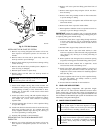
B. INSTALL LIQUID-LINE FILTER DRIER
Installation of filter drier in liquid line is required. Refer to Fig. 7
and install filter drier as follows:
1. Braze 5-in. connector tube to liquid service valve. Wrap
filter drier with damp cloth.
2. Braze filter drier between connector tube and liquid tube to
indoor coil. Flow arrow must point toward indoor coil.
C. REFRIGERANT TUBING
Connect vapor tube to fitting on outdoor unit vapor service valves.
Connect liquid tube to filter drier. (See Fig. 7 and Table 1.) Use
refrigerant grade tubing.
CAUTION: To avoid valve damage while brazing, ser-
vice valves must be wrapped in heat-sink material, such
as a wet cloth.
D. SWEAT CONNECTION
Service valves are closed from factory and ready for brazing. After
wrapping service valve and filter drier with a wet cloth, braze
sweat connections using industry accepted methods and materials.
Do not use soft solder (materials which melt below 800°F).
Consult local code requirements. Refrigerant tubing and indoor
coil are now ready for leak testing. This check should include all
field and factory joints.
IMPORTANT: Check factory tubing on both indoor and outdoor
unit to ensure tubes are not rubbing against each other or any sheet
metal. Pay close attention to feeder tubes making sure wire ties on
feeder tubes are secure and tight.
E. LEAK CHECKING
Leak test all joints in indoor, outdoor, and refrigerant tubing.
F. EVACUATE REFRIGERANT TUBING AND INDOOR
COIL
CAUTION: Never use the system compressor as a
vacuum pump.
Refrigerant tubes and indoor coil should be evacuated using the
recommended deep vacuum method of 500 microns. The alternate
triple evacuation method may be used if the procedure outlined
below is followed. Always break a vacuum with dry nitrogen.
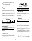
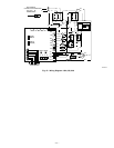
DEEP VACUUM METHOD
The deep vacuum method requires a vacuum pump capable of
pulling a vacuum of 500 microns and a vacuum gage capable of
accurately measuring this vacuum depth. The deep vacuum
method is the most positive way of assuring a system is free of air
and liquid water. (See Fig. 8.)
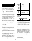
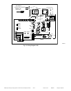
TRIPLE EVACUATION METHOD
The triple evacuation method should only be used when vacuum
pump is capable of pumping down to 28 in. of mercury and system
does not contain any liquid water. Refer to Fig. 9 and proceed as
follows:
1. Pump system down to 28 in. of mercury and allow pump to
continue operating for an additional 15 minutes.
2. Close service valves and shut off vacuum pump.
3. Connect a nitrogen cylinder and regulator to system and
open until system pressure is 2 psig.
4. Close service valve and allow system to stand for 1 hr.
During this time, dry nitrogen will be able to diffuse
throughout the system, absorbing moisture.
5. Repeat this procedure as indicated in Fig. 9. System will
then contain minimal amounts of contaminants and water
vapor.
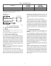
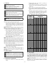
TABLE 1—REFRIGERANT CONNECTIONS AND
RECOMMENDED LIQUID AND VAPOR TUBE
DIAMETERS (IN.)
UNIT
SIZE
LIQUID VAPOR VAPOR (LONG-LINE)
Connection
Diameter
Tube
Diameter
Connection
Diameter
Tube
Diameter
Connection
Diameter
Tube
Diameter
024 3/8 3/8 5/8 5/8 5/8 3/4
036 3/8 3/8 3/4 3/4 3/4 7/8
048 3/8 3/8 7/8 7/8 7/8 7/8
060 3/8 3/8 7/8 1-1/8 7/8 1-1/8
Notes:
1. Tube diameters are for lengths up to 50 equivalent ft.
2. Do not apply capillary tube indoor coils to these units.
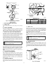
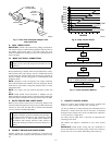
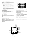
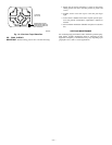
Fig. 6—Positioning of Sensing Bulb
A02000
SENSING BULB
STRAP
8 O'CLOCK
4 O'CLOCK
SUCTION
TUBE
—4—