


INSTALLATION
I. CHECK EQUIPMENT AND JOB SITE
A. UNPACK UNIT
Move to final location. Remove carton, taking care not to damage
unit.
B. INSPECT EQUIPMENT
File claim with shipping company prior to installation if shipment
is damaged or incomplete. Locate unit rating plate on unit corner
panel. It contains information needed to properly install unit.
Check rating plate to be sure unit matches job specifications.
II. INSTALL ON A SOLID, LEVEL MOUNTING PAD
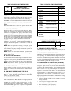
If conditions or local codes require the unit be attached to pad, tie
down bolts should be used and fastened through knockouts
provided in unit base pan. Refer to unit mounting pattern in Fig. 3
to determine base pan size and knockout hole location.
On rooftop applications, mount on level platform or frame. Place
unit above a load-bearing wall and isolate unit and tubing set from
structure. Arrange supporting members to adequately support unit
and minimize transmission of vibration to building. Consult local
codes governing rooftop applications.
CAUTION: Do not allow POE lubricant to come into
contact with roofing material. POE may deteriorate cer-
tain types of synthetic roofing.
Roof mounted units exposed to winds above 5 mph may require
wind baffles. Consult the Application Guideline and Service
Manual for Residential Split System Air Conditioners and Heat
Pumps using Puron® Refrigerant for wind baffle construction
NOTE: Unit must be level to within ±2° (±3/8 in./ft) per
compressor manufacturer specifications.
III. CLEARANCE REQUIREMENTS
When installing, allow sufficient space for airflow clearance,
wiring, refrigerant piping, and service. Allow 30-in. clearance to
service end of unit and 48 in. above unit. For proper airflow, a 6-in.
clearance on 1 side of unit and 12 in. on all remaining sides must
be maintained. Maintain a distance of 24 in. between units.
Position so water, snow, or ice from roof or eaves cannot fall
directly on unit.
IV. OPERATING AMBIENTS
The minimum outdoor operating ambient in cooling mode is 55°F,
and the maximum outdoor operating ambient in cooling mode is
125°F.
V. INSTALL TXV
Puron® fan coils and furnace coils come factory equipped with a
bi-flow, hard shut off TXV specifically designed for Puron®
two-speed units. No TXV changeout is required. An existing R-22
TXV must be replaced with a factory approved TXV specifi-
cally designed for Puron® two-speed units.
NOTE: FK4 and FC4 fan coils are equipped with an R-22 TXV.
If an FK4 or an FC4 fan coil is used with a Puron® air conditioner,
the R-22 TXV must be replaced with a factory-approved Puron®
TXV.
CAUTION: If indoor unit is equipped with piston,
remove indoor coil piston and replace with factory
approved TXV metering device.
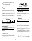
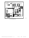
A. TXV INSTALLATION
IMPORTANT: The TXV should be mounted as close to the
indoor coil as possible and in a vertical, upright position. Avoid
mounting the inlet tube vertically down. Valve is more susceptible
to malfunction due to debris if inlet tube is facing down. A factory
approved filter drier must be installed in the liquid line. (See Fig.
4.)
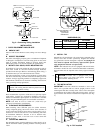
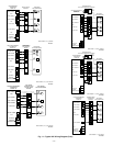
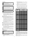
Fig. 2—Connecting Tubing Installation
A01383
INSULATION
VAPOR TUBE
LIQUID TUBE
OUTDOOR WALL INDOOR WALL
LIQUID TUBE
VAPOR TUBE
INSULATION
CAULK
Avoid contact between tubing and structureNOTE:
THROUGH THE WALL
HANGER STRAP
(AROUND VAPOR
TUBE ONLY)
JOIST
1″ MIN.
SUSPENSION
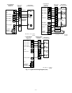
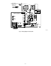
Fig. 3—Mounting Unit to Pad
DIMENSIONS (IN.)
UNIT SIZE
MINIMUM MOUNTING
PAD DIMENSIONS
TIEDOWN KNOCKOUT
LOCATIONS
AB
024 19 X 24 2-13/16 6-15/16
036-060 26 X 32 4 9-3/4
A97375
B
A
L
C
8
3
⁄16″
3
⁄8 IN. DIA TIEDOWN
KNOCKOUTS
(2) PLACES
IN BASEPAN
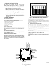
THERMOSTATIC
EXPANSION
VALVE
EQUALIZER
TUBE
SENSING
BULB
COIL
A91277
Fig. 4—TXV Installed
—2—
→