


—8—
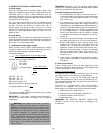
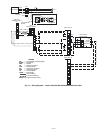
Table 4 — Refrigerant Specialties Part Numbers
*A filter drier is shipped loose with the 575B072 units.
†Bushings required.
**Factory Installed.
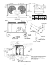
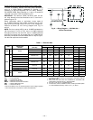
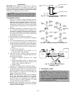
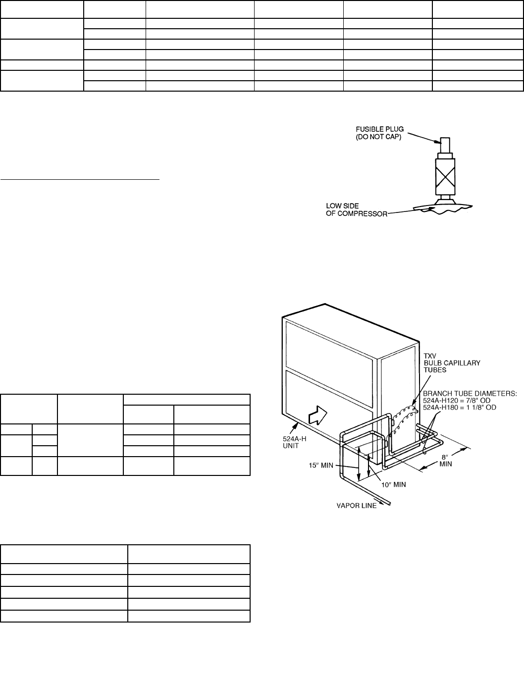
F. Provide Safety Relief
A fusible plug is located on the compressor crankcase or in
the liquid line. See Fig. 6. Do not cap this plug. If local code
requires additional safety devices, install them as directed.
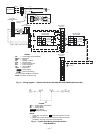
Head Pressure Control (541A180 only)
Fan cycling for head pressure control is a standard offering
but is functional on the cooling cycle only. Number 2 fan
cycles as a function of liquid pressure. Fan cycling pressure
switch cycles the fan off at 160 ± 10 psig as pressure
decreases and cycles back on at 255 ± 10 psig. Switch is auto-
matically bypassed in heating cycle. Table 5 shows minimum
outdoor air temperature for full cooling capacity.
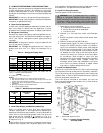
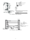
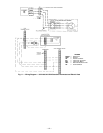
G. Vapor Line Piping Procedure
Connect system vapor line to the vapor line stub on the out-
door unit and the vapor stubs on the indoor unit. At the
indoor unit, construct vapor piping branches as shown in
Fig. 7 for good mixing of the refrigerant leaving the indoor
coil during cooling. This will ensure proper TXV (thermo-
static expansion valve) bulb sensing.
Where vapor line is exposed to outdoor air, line must be insu-
lated. See Table 6 for insulation requirements.
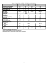
Table 5 — Minimum Outdoor Air
Operating Temperature
*Applies to Cooling mode of operation only.
†Wind baffles (field-supplied and field-installed) are recommended for
all units with low ambient head pressure control. Refer to Low Ambient
Control Installation Instructions (shipped with accessory) for details.
Table 6 — Insulation for Vapor Line Exposed
to Outdoor Conditions
*Recommended vapor line insulation for piping exposed to outdoor
conditions to prevent loss of heating during heating cycle. When vapor
line goes through interior spaces, insulation should be selected to pre-
vent condensation on cooling cycle. Heating capacity should be
reduced 1000 Btuh if over 35 ft of vapor line with
3
/
4
in. insulation is
exposed to outdoor conditions.
†Closed cell foam insulation with a thermal conductivity of: 0.28 Btu
• in./ft
2
• h • °F.
UNIT
LIQUID LINE
SIZE
LIQUID LINE
SOLENOID VALVE (LLSV)
LLSV COIL SIGHT GLASS FILTER DRIER
575B072
1
/
2
″ 200RB GS-1928 5T4 AMG-24/50-60 AMI1TT4 *
5
/
8
″ 200RB GS-1929 5T5 AMG-24/50-60 AMI1TT5 *
575C090
3
/
8
″ 200RB GS-1928 5T4† AMG-24/50-60 AMI1TT3 P504-8083S
1
/
2
″ 200RB GS-1928 5T4 AMG-24/50-60 AMI1TT4 P504-8084S
575C120
1
/
2
″ 200RB GS-1928 5T4 AMG-24/50-60 AMI1TT4 P504-8164S
541A180
5
/
8
″ ** ** AMI1TT5 P504-8085S Qty 2
3
/
4
″ ** ** AMI1TT5 P504-8085S Qty 2
UNIT
%
COMPRESSOR
CAPACITY
MINIMUM OUTDOOR TEMP — F*
Standard
Unit
Head Pressure
Control†
575B 072
100
00
575C
090 35 –20
120 35 –20
541A 180
100
67
23
36
–20
–20
LENGTH OF EXPOSED
VAPOR LINE*
INSULATION THICKNESS†
ft in.
10
3
/
8
25
1
/
2
35
3
/
4
50
3
/
4
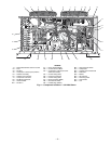
Fig. 6 — Location of Fusible Plug —
541A180 Unit
LEGEND
Fig. 7 — Vapor Line Branch Piping Details
TXV — Thermostatic Expansion Valve