


—19—
When the thermostat is satisfied, contacts open, deenergiz-
ing C. The COMP, IFM, and OFM stop.
B. Heating
On a call for heat, thermostat makes circuits R-Y and R-G.
When compressor time delay (5 ± 2 minutes) is completed, a
circuit is made to C, starting COMP and OFM. Circuit R-G
also energizes IFC and starts IFM after a 1-second delay.
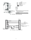
III. 541A180 UNITS
A. Heating
Place thermostat selector at HEAT and set temperature
selector above room ambient.
B. Cooling
Place thermostat selector at COOL and set temperature
selector below room ambient.
When thermostat calls for unit operation (either heating or
cooling), the indoor-fan motor starts immediately. The
outdoor-fan motors and compressor start within 3 seconds to
5 minutes depending on when unit was last shut off by ther-
mostat, because unit contains a compressor time delay cir-
cuit. When first-stage cooling is required, thermostat (TC1)
closes, causing the heat pump to start with an unloaded com-
pressor. When TC2 closes, demanding additional cooling, the
compressor loads to full load operation.
During heating, compressor is always fully loaded. When
TH1 demands first-stage heating, the heat pump starts
within 3 seconds to 5 minutes depending on when unit was
last shut off by thermostat, because unit contains a compres-
sor time delay circuit. (The defrost board has speed termi-
nals to shorten this cycle.) When TH2 of the thermostat
closes, auxiliary heat supply (electric strip heat) is energized
in 1 or 2 stages depending on number of stages available and
whether outdoor thermostats are closed.
Defrost is achieved by reversal from heating to cooling cycle
and deenergization of outdoor-fan motors, allowing hot
refrigerant gas to defrost outdoor coil. Defrost is achieved
with a timer set to initiate defrost every 30, 50, or
90 minutes (factory set at 30 minutes).
Defrost is initiated when refrigerant temperature leaving
the outdoor coil is measured below 27 F, (typically when the
outdoor ambient temperature is below 45 F as sensed by the
defrost thermostat [DFT]).
Defrost is terminated when: The refrigerant temperature
rises to 80 F at the DFT location on the liquid line; or the
refrigerant pressure rises to 280 psig at the HPS2 location
on the liquid line; or the defrost timer completes the
10-minute cycle.
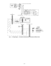
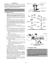
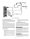
IV. DUPLEX UNITS
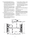
A. Duplex 575C120 Units with 524A-H240 (See Fig. 12)
Cooling
When the thermostat is set for cooling, and the space tem-
perature comes within 2° F of the cooling set point, the ther-
mostat completes the circuit from R to O and the reversing
valves in both units are energized. If the space temperature
continues to rise, the circuit from R to Y1 is completed. If the
time delays and safeties are satisfied, the compressor contac-
tor closes, starting the compressor and outdoor-fan motors of
Heat Pump A. At the same time the circuit is completed from
R to G, starting the indoor-fan motor. If the space tempera-
ture continues to rise, the circuit is completed from R to
Y2 and the Cooling mode is initiated in Heat Pump B in a
similar manner.
When the thermostat is satisfied, the contacts open, deener-
gizing first the Heat Pump B and then Heat Pump A.
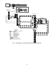
Heating
When the thermostat calls for heating, the circuit from R to
Y1 is completed. If the time delays and safeties are satisfied,
the compressor contactor closes, starting the compressor and
outdoor-fan motors of Heat Pump A and Heat Pump B. At
the same time the circuit is completed from R to G, starting
the indoor-fan motor. If the second stage of heating is
required, the circuit from R to W2 will be completed and the
electric resistance heaters will be energized.
When the thermostat is satisfied, the contacts open, deener-
gizing Heat Pump A and Heat Pump B.
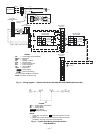
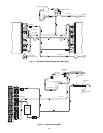
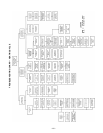
B. Duplex 575C120 and 541A180 Units With 524A-H300
(See Fig. 13)
Cooling
When the thermostat calls for cooling, the circuit from R to
Y1 is completed. If the time delays and safeties are satisfied,
the compressor contactor closes, starting the compressor and
outdoor-fan motors of Heat Pump A (541A180). At the same
time the circuit is completed from R to G, starting the indoor-
fan motor. If the space temperature continues to rise, the
circuit is completed from R to Y2 and the Cooling mode is
initiated in Heat Pump B (575C120).
When the thermostat is satisfied, the contacts open, deener-
gizing first the Heat Pump B and then Heat Pump A.
Heating
When the thermostat calls for heating, the circuit from R to
W1 is completed. If the time delays and safeties are satisfied,
the compressor contactor closes, starting the compressor and
outdoor-fan motors of Heat Pump A and Heat Pump B. At
the same time the circuit is completed from R to G, starting
the indoor-fan motor. If the second stage of heating is
required, the circuit from R to W2 will be completed and the
electric resistance heaters will be energized.
When the thermostat is satisfied, the contacts open, deener-
gizing Heat Pump A and Heat Pump B.
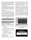
C. Safeties
The high-pressure switch, loss-of-charge switch, oil pressure
safety switch, and compressor overtemperature safety are
located in a CLO circuit that prevents heat pump operation
if these safety devices are activated. A light at the thermo-
stat energizes when CLO circuit is affected. The lockout sys-
tem can be reset by adjusting the thermostat to open the
contacts (down for Heating mode, up for Cooling mode),
deenergizing the CLO circuitry. Compressor overcurrent pro-
tection is achieved with a circuit breaker which requires
manual resetting at the outdoor unit control box.
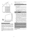
The unit is equipped with an oil pressure safety switch that
protects the compressor if oil pressure does not develop on
start-up or is lost during operation. The oil pressure switch
is of the manual reset type and therefore must be reset at
the outdoor unit. DO NOT RESET MORE THAN ONCE.
If oil pressure switch trips, determine cause and correct. DO
NOT JUMPER OIL PRESSURE SAFETY SWITCH.
To reset the oil pressure switch:
1. Disconnect power to the unit.
2. Press the RESET button on the oil pressure switch.
3. Reconnect power to the unit.