


—20—
Unit is equipped with a no-dump reversing valve circuit.
When unit is in Cooling mode, reversing valve remains in
cooling position until a call for heating is requested by ther-
mostat. When unit is in Heating mode, reversing valve
remains in heating position until there is a call for cooling.
The crankcase heater is in a lockout circuit. If crankcase
heater is defective, compressor is locked off. Heat pump
remains off until corrective action is taken. The lockout cir-
cuit cannot be reactivated by adjusting the thermostat. To
reset the crankcase heater lockout, disconnect and then
reconnect power to unit.
D. Check Operation
Ensure operation of all safety controls. Replace all service
panels. Be sure that control panel cover is closed tightly.
V. RESTART
Manual reset of the 24-v control circuit is necessary if unit
shutdown is caused by automatic reset devices (including IP
[internal compressor overcurrent protection], HPS [high-
pressure switch], and LCS [loss-of-charge switch]) or if
shutdown is caused by manual reset devices (including
OPS [oil pressure switch] and compressor circuit breaker
protection). To restart the unit when IP, HPS, or LCS has
tripped (after device has reset automatically), open and then
close the thermostat contacts. Opening and then closing
thermostat contacts interrupts and restores 24-v power to
the compressor lockout (CLO), which resets the circuit.
It is necessary to manually reset the compressor circuit
breaker and OPS at the unit if either of these safeties should
shut down the unit.
IMPORTANT: If OPS trips, it must be reset first before mak-
ing and breaking the thermostat contacts to reset CLO. If
this procedure is not followed, the CLO cannot reset.
VI. CAUSES OF COMPLETE UNIT SHUTDOWN:
• interruption of supplied power
• open compressor overtemperature protection (IP)
• compressor electrical overload protection (CB)
• open high-pressure or loss-of-charge safety switches
• open oil pressure switch
• open crankcase heater lockout (CLO2)
• open control circuit fuse (FU1 or FU2)
• open discharge gas thermostat (575C only)
SERVICE
I. COMPRESSOR REMOVAL
See Table 1 for compressor information. Follow safety codes
and wear safety glasses and work gloves.
1. Shut off power to unit. Remove unit access panel.
2. Recover refrigerant from system using refrigerant
recovery methods, and in accordance with local and
national standards.
3. Disconnect compressor wiring at compressor termi-
nal box.
4. Disconnect refrigerant lines from compressor.
5. Remove screws from compressor mounting plate.
6. Remove or disconnect crankcase heater from com-
pressor base.
7. Remove compressor from unit.
8. On 541A180 unit remove compressor holddown bolts
and lift compressor off mounting plate.
9. Clean system. Add new liquid line filter drier.
10. Install new compressor on compressor mounting
plate and position in unit. Connect suction and dis-
charge lines to compressor. Secure mounting plate
with compressor to unit. Ensure that compressor
holddown bolts are in place. Connect wiring. Install
crankcase heater.
11. Evacuate and recharge unit.
12. Restore unit power.
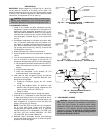
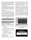
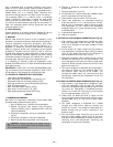
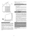
II. 575C090,120 COOLING MODE OPERATION (See Fig. 20)
1. High pressure, high temperature refrigerant vapor
from the compressor flows through the reversing
valve and is directed to the vapor headers of both
outdoor coils.
2. At the outdoor coil vapor header, the high pressure,
high temperature refrigerant vapor flows up to check
valve “A” that blocks the flow. All the refrigerant is
then directed to flow into the coil circuits.
3. Subcooled refrigerant liquid leaves the coil circuits
through the side outlet on the liquid headers. The
liquid refrigerant from each coil flows through check
valves “B” which are open, enters the liquid line and
goes to the indoor coil.
4. The liquid refrigerant is expanded and evaporated in
the indoor coil resulting in low pressure vapor. This
low pressure vapor returns to the outdoor unit
through the system vapor line, reversing valve, and
accumulator, reentering the compressor at the suc-
tion connection.
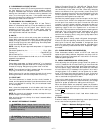
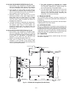
III. 575C090,120 HEATING MODE OPERATION (See Fig. 21)
1. High pressure, high temperature refrigerant vapor
from the compressor flows through the reversing
valve and is directed through the system vapor line to
the indoor coil. Refrigerant is condensed and sub-
cooled in the indoor coil and returns to the outdoor
unit through the system liquid line.
2. Check valve “B” blocks the flow of liquid and the
liquid refrigerant must flow through the filter driers,
through check valve “C”, and into the liquid header
assembly.
3. The liquid refrigerant is expanded as it passes
through the fixed orifice metering devices into
outdoor coil circuits. The refrigerant evaporates as it
passes through the coil circuits resulting in low
pressure vapor.
4. The low pressure vapor leaves the coil circuits and
enters the vapor headers, check valves “A” are open,
and returns to the compressor through the vapor line,
reversing valve, and accumulator, reentering the
compressor at the suction connection.
CAUTION: Excessive movement of copper lines at
compressor may cause higher levels of vibration when
unit is restored to service.