


—17—
IV. COMPRESSOR LOCKOUT DEVICE
The compressor lockout (CLO) device prevents the compres-
sor from starting or running in a high pressure, loss-of-
charge or freezestat open situation. Reset the CLO device by
setting the thermostat to eliminate cooling demand and
return it to the original set point. If the system shuts down
again for the same fault, determine the possible cause before
attempting to reset the CLO device.
V. PRELIMINARY OIL CHARGE (541A)
The compressor is factory charged with oil (see Table 1).
When oil is checked at start-up, it may be necessary to add or
remove oil to bring it to the proper level. Add oil only if
necessary to bring oil into view in sight glass. Use only
Bryant-approved compressor oil. One recommended oil
level adjustment method is as follows:
A. Add Oil
Close suction service valve and pump down crankcase to
2 psig. Wait a few minutes and repeat until pressure remains
steady at 2 psig. Remove oil fill plug above the sight glass,
add oil through plug hole, and replace plug. Run compressor
for 20 minutes and check oil level.
NOTE: Use only Bryant-approved compressor oil. Approved
sources are:
Petroleum Specialties, Inc.. . . . . . . . . . . . . . . . . . . Cryol 150A
Texaco, Inc. . . . . . . . . . . . . . . . . . . . . . . . . . . . . Capella WF-32
Witco Chemical Co.. . . . . . . . . . . . . . . . . . . . . . . . .Suniso 3GS
Do not use oil that has been drained out, or oil that has been
exposed to atmosphere.
B. Remove Oil
Pump down compressor to 2 psig. Loosen the
1
/
4
-in. pipe plug
at the compressor base and allow the oil to seep out past the
threads of the plug. Retighten plug when level is correct.
NOTE: The crankcase is slightly pressurized. Do not remove
the plug, or the entire oil charge will be lost.
Small amounts of oil can be removed through the oil pump
discharge connection while the compressor is running.
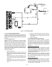
VI. START UNIT
The field disconnect is closed, the fan circuit breaker is
closed, and the space thermostat is set above ambient so that
there is no demand for cooling. Only the crankcase heater
will be energized.
Next, close the compressor circuit breaker and then reset
space thermostat below ambient so that a call for cooling is
ensured.
NOTE: Do not use circuit breaker to start and stop the com-
pressor except in an emergency.
After starting, there is a delay of at least 3 seconds before
compressor starts.
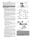
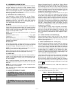
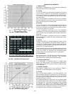
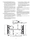
VII. ADJUST REFRIGERANT CHARGE
Refer to Charging Charts Fig. 19A-19C and Table 8. Do not
exceed maximum refrigerant charge. Vary refrigerant until
the conditions of the chart are met. Note that charging
charts are different from type normally used. Charts are
based on charging the units to the correct subcooling for the
various operating conditions. Accurate pressure gage and
temperature sensing device are required.
Connect the pressure gage to the service port on the liquid
line service valve. Mount the temperature sensing device
on the liquid line, close to the liquid line service valve and
insulate it so that outdoor ambient temperature does not
affect the reading. Indoor airflow must be within the normal
operating range of the unit. Operate unit a minimum of
15 minutes. Ensure pressure and temperature readings have
stabilized. Plot liquid pressure and temperature on chart
and add or reduce charge to meet curve. Adjust charge to
conform with charging chart, using the liquid pressure and
temperature to read chart.
If the sight glass is cloudy, check refrigerant charge again.
Ensure all fans are operating. Also ensure maximum allow-
able liquid lift has not been exceeded. If charged per chart
and if the sight glass is still cloudy, check for a plugged filter
drier or a partially closed solenoid valve. Replace or repair,
as needed.
VIII. CHECK HEATING CYCLE OPERATION
Place thermostat selector switch at HEAT and reset the
space set point above ambient temperature so that a call for
heating is ensured. Compressor will start within 5 minutes.
Observe system operation.
IX. CHECK COMPRESSOR OIL LEVEL (541A)
After adjusting the refrigerant charge, allow the system to
run fully loaded for 20 minutes. Running oil level should be
within view in the crankcase sight glass. Stop compressor at
the field power supply disconnect and check the crankcase
oil level. Add oil only if necessary to bring the oil into view in
the sight glass. If oil is added, run the system for an addi-
tional 10 minutes, then stop and check oil level. If the level
remains low, check the piping system for proper design for oil
return; also check the system for leaks.
If the initial check shows too much oil (too high in the sight
glass) remove oil to proper level. See Preliminary Oil Charge
section for proper procedure for adding and removing oil.
When the above checks are complete, repeat the procedure
with the unit operating at minimum load conditions. Unload
the compressor by disconnecting the field-control circuit lead
at TB2 .
Reconnect the field-control circuit lead when checks are
complete.
X. FINAL CHECKS
Ensure all safety controls are operating, control panel covers
are on, and the service panels are in place.
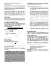
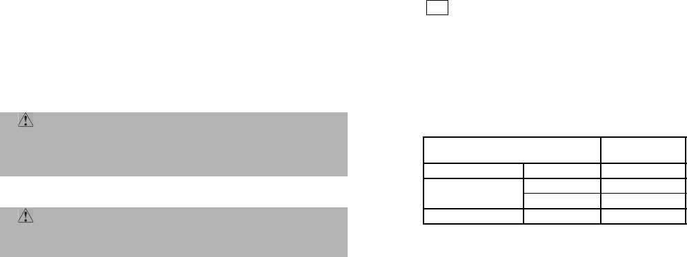
Table 8 — Maximum Refrigerant Charge
CAUTION: Never charge liquid into the low-
pressure side of system. Do not overcharge. During
charging or removal of refrigerant, be sure indoor-fan
system is operating.
CAUTION: Charge unit on cooling cycle only. If
unit is charged on heating cycle, overcharging may
occur.
UNIT
R-22
(lb)
575B 072 27.0
575C
090 34.2
120 34.2
541A 180 62.0
Y2