


—21—
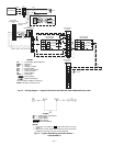
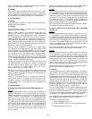
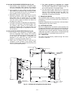
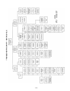
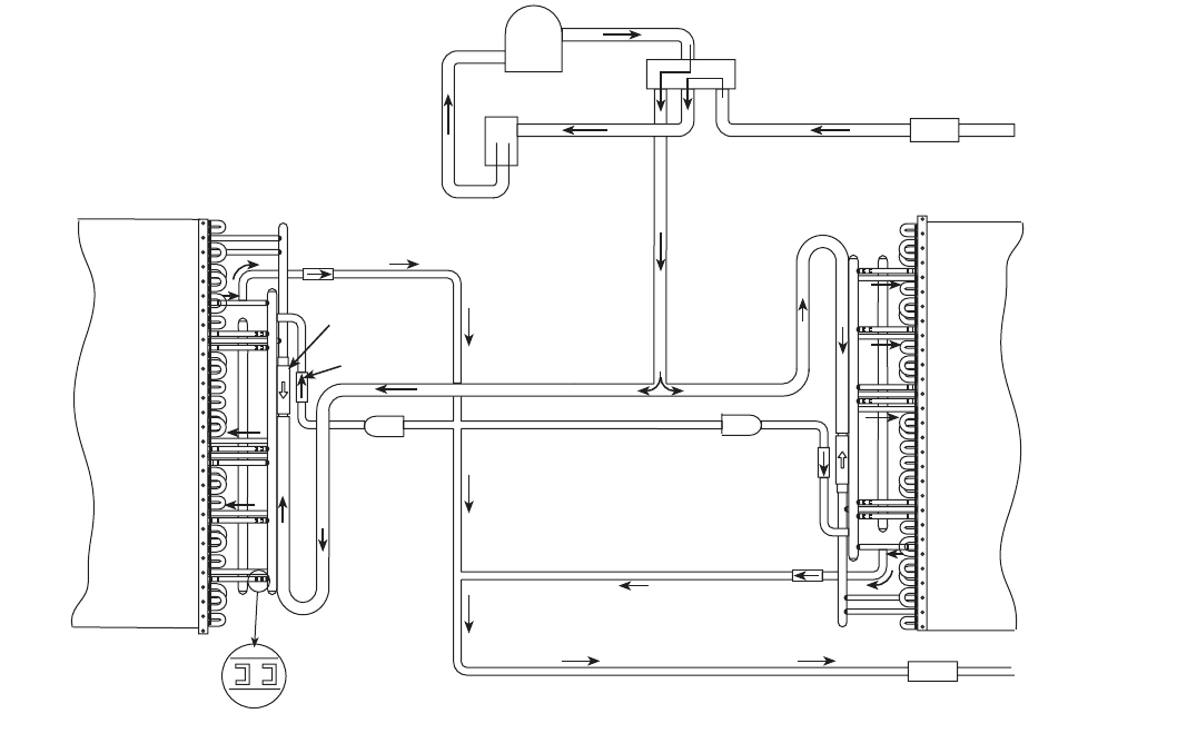
IV. 541A180 COOLING MODE OPERATION (See Fig. 22)
1. High pressure, high temperature refrigerant vapor
from the compressor flows through the reversing
valve and is directed to the outdoor coil vapor header.
2. At the outdoor coil vapor header, the high pressure,
high temperature refrigerant vapor flows up to check
valve “A” that blocks the flow. All the refrigerant is
then directed to flow into the coil circuits.
3. Subcooled refrigerant liquid leaves the coil circuits
entering the portion of the vapor header which is
above check valve “A”. Check valve “C” is closed,
therefore, the liquid refrigerant passes through check
valve “B,” which is open, and enters the liquid line
and goes to the indoor coil.
4. The liquid refrigerant is expanded and evaporated in
the indoor coil resulting in low pressure vapor. This
low pressure vapor returns to the outdoor unit
through the system vapor line, reversing valve, and
accumulator, reentering the compressor at the suc-
tion connection.
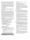
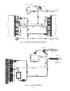
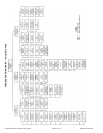
V. 541A180 HEATING MODE OPERATION (See Fig. 23)
1. High pressure, high temperature refrigerant vapor
from the compressor flows through the reversing
valve and is directed through the system vapor line
to the indoor coil. Refrigerant is condensed and
subcooled in the indoor coil and returns to the
outdoor unit through the system liquid line.
2. Check valve “B” blocks the flow of liquid and the
refrigerant is then directed to flow through check
valve “C” (which is open), through the filter drier, and
into the liquid header assembly.
3. The liquid refrigerant is expanded as it passes
through the capillary tubes into outdoor coil circuits.
The refrigerant evaporates as it passes through the
coil circuits resulting in low pressure vapor.
4. The low pressure vapor leaves the coil circuits and
enters the vapor header, check valve “A” is open, and
returns to the compressor through the vapor line,
reversing valve, and accumulator, reentering the
compressor at the suction connection.
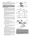
VI. CRANKCASE HEATER
The crankcase heater prevents refrigerant migration and
compressor oil dilution during shutdown when compressor is
not operating.
Close both compressor service valves when crankcase heater
is deenergized for more than 6 hours.
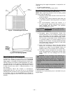
VII. OUTDOOR UNIT FANS
Each fan is supported by a formed-wire mount bolted to the
fan deck and covered with a wire guard. On the 541A180, the
exposed end of the motor shaft is covered with a rubber boot.
In case a fan motor must be repaired or replaced, be sure the
rubber boot is put back on when the fan is reinstalled and be
sure the fan guard is in place before starting the unit.
VIII. LUBRICATION
Fan motors have permanently sealed bearings. No further
lubrication is required.
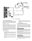
ACCUMULATOR
COMPRESSOR
REVERSING VALVE
VAPOR LINE
BALL
VALVE
FROM
INDOOR
UNIT
FILTER
DRIER
LIQUID LINE
BALL
VALVE
TO
INDOOR
UNIT
FIXED ORIFICE
METERING DEVICE
FILTER
DRIER
CK VALVE C
CK VALVE A
CK VALVE B
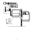
Fig. 20 — 575C090,120 Cooling Mode (Size 090 Shown)