


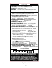
flashing, or a code composed of 2 digits. (The first digit is the
number of short flashes, the second is the number of longs flashes.)
Refer to service label on blower compartment door for code
explanations and useful troubleshooting suggestions. (See Fig. 12.)
It is important to note that power to furnace must not be interrupted
and furnace blower door must not be removed until the LED status
code(s) is recorded. When power to control is interrupted, status
memory is erased.
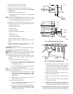
The control will store up to 5 previous codes but will not store
non-current codes longer than 48 hr. To retrieve previous codes, if
present, no thermostat inputs to control must be present and all
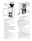
time delays must expire. Remove 1 of the red main limit wires 1
to 4 sec until the LED light goes out, then reconnect it. (See Fig.
5 and 6.) (Do not leave red wire disconnected for longer than 4 sec
as control will assume an overtemperature condition exists and
will respond with indoor blower operation.) This places control in
status recall mode and displays first code stored in memory.
Record code and repeat the disconnect and reconnect of red wire,
recording each code until code 11 is displayed indicating no
additional faults. After last code is displayed or after 2 minutes in
the code recall mode, the control will return to normal standby
mode.
Use any recorded fault codes, service label, and troubleshooting
diagram on following pages to diagnose and correct any problem
condition.
WIRING DIAGRAMS
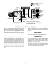
Refer to Fig. 9, 10, and 11 for appropriate wiring diagrams.
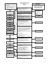
TROUBLESHOOTING
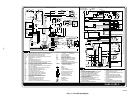
Refer to service label. (See Fig. 12.) The Troubleshooting Guide
can be a useful tool in isolating furnace operation problems.
Beginning with the word “Start,” answer each question and follow
the appropriate arrow to the next item.
The Guide will help you identify the problem or failed component.
After replacing any component, verify correct operation sequence.
More information is available in a seperate Troubleshooting Guide
for 2-stage Gas-Fired Induced-Combustion Furnaces.
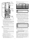
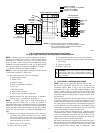
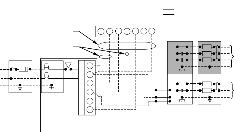
Fig. 10—Heating and Cooling Application Wiring Diagram
for 2-Stage Thermostats and/or 2-Speed Condensing Units
A99072
115-V FUSED
DISCONNECT
SWITCH
(WHEN REQUIRED)
JUNCTION
BOX
CONTROL
BOX
24-V
TERMINAL
BLOCK
THREE-WIRE
HEATING-
ONLY
SEVEN
WIRE
2-STAGE THERMOSTAT TERMINALS
FIELD-SUPPLIED
FUSED DISCONNECT
2-SPEED
CONDENSING
UNIT
FURNACE
G
R
W2 Y2 G Y1
C
GND
GND
GND
GND
GND
GND
FIELD 24-V WIRING
FIELD 115-, 208/230-, 460-V WIRING
FACTORY 24-V WIRING
FACTORY 115-V WIRING
208/230- OR
460-V
THREE
PHASE
208/230-V
SINGLE
PHASE
Y2
Y1
C
WHT
BLK
WHT
BLK
W1 R
W2
COM
W/W1
Y/Y2
NOTES: 1. Connect Y-terminal as shown for proper operation.
2. Some thermostats require a "C" terminal connection as shown.
3. If any of the original wire, as supplied, must be replaced,
use same type or equivalent wire.
—7—