


7. Remove screws holding blower assembly to blower deck
and slide blower assembly out of furnace.
8. Clean blower wheel and motor using a vacuum with soft
brush attachment. Do not remove or disturb balance weights
(clips) on blower wheel blades. The blower wheel should
not be dropped or bent as balance will be affected.
9. If greasy residue is present on blower wheel, remove wheel
from the blower housing and wash it with an appropriate
degreaser. To remove wheel:
a. Mark blower wheel location on shaft before disassembly
to ensure proper reassembly.
b. Loosen setscrew holding blower wheel on motor shaft.
NOTE: Mark blower mounting arms, motor, and blower housing
so motor and each arm is positioned at the same location during
reassembly.
c. Mark blower wheel orientation and cutoff plate location
to ensure proper reassembly.
d. Remove screws securing cutoff plate and remove cutoff
plate from housing.
e. Remove bolts holding motor mounts to blower housing
and slide motor and mounts out of housing. Disconnect
capacitor and ground wire attached to blower housing
before removing motor.
f. Remove blower wheel from housing.
10. Reassemble motor and blower by reversing items 9a
through 9f. Be sure to reattach ground wire.
11. Reinstall blower assembly in furnace.
12. Reinstall control box and support assembly in furnace.
13. Reconnect blower leads to furnace control and auxiliary
limit switch leads (downflow only).
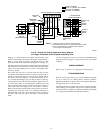
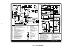
Refer to furnace wiring diagram, and connect thermostat
leads if previously disconnected. (See Fig. 11.)
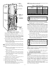
NOTE: Refer to Table 1 for motor speed lead relocation if leads
were not identified before disconnection.
CAUTION: Heating speed selection MUST be adjusted
to provide proper temperature rise as specified on the
rating plate. Failure to adjust the heating speed may
shorten heat exchanger life.
14. Reinstall internal vent pipe and enclosure on downflow
furnaces only by reversing items 3a through 3c.
NOTE: A releasing agent such as PAM cooking spray or equiva-
lent (must not contain corn or canola oil, aromatic or halogenated
hydrocarbons or inadequate seal may occur) and RTV sealant
(G.E. 162, 6702, or Dow-Corning 738) are needed before starting
installation. DO NOT substitute any other type of RTV sealant.
G.E. 162 (P771-9003) is available through RCD in 3-oz tubes.
15. Reinstall vent connector to furnace flue collar. After fully
assembling vent connector to furnace flue collar, securely
fasten vent connector to flue collar with 2 field-supplied,
corrosion-resistant, sheet metal screws located 180 degrees
apart and midway up the collar.
16. Turn on electrical supply. Manually close blower access
door switch. Use a piece of tape to hold switch closed.
Check for proper rotation and speed changes between
heating and cooling by jumpering R to W and then R to Y
on furnace control thermostat terminals.
WARNING: Blower access door switch opens 115-v
power to furnace control. No component operation can
occur. Caution must be taken when manually closing this
switch for service purposes. Failure to follow this warn-
ing could result in electrical shock, personal injury, or
death.
NOTE: If thermostat terminals are jumpered before blower ac-
cess door switch is closed, blower will run for 90 sec before
beginning a heating or cooling cycle.
17. If furnace is operating properly, remove tape to release
blower access door switch, replace blower access door.
III. CLEANING HEAT EXCHANGER
The following steps should be performed by a qualified service
technician:
NOTE: If the heat exchangers get a heavy accumulation of soot
and carbon, they should be replaced rather than trying to clean
them thoroughly due to their intricate design. A build-up of soot
and carbon indicates that a problem exists which needs to be
corrected, such as improper adjustment of manifold pressure,
insufficient or poor quality combustion air, incorrect size, or
damaged manifold orifice(s), improper gas, or a restricted heat
exchanger. Action must be taken to correct the problem.
If it becomes necessary to clean heat exchanger because of light
dust or corrosion proceed as follows:
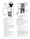
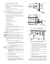
Fig. 6—Model 331JAV Downflow
A99092
PRESSURE
SWITCHES
VENT PIPE
ENCLOSURE
CONTROL
FLUE
COLLAR
DRAFT
SAFEGUARD
SWITCH
AUXILIARY
LIMIT
SWITCH
MANUAL
RESET
LIMIT
SWITCHES
RELIEF
BOX
MOUNTING
SCREWS
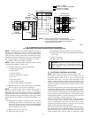
TABLE 1—SPEED SELECTOR
COLOR SPEED
FACTORY-
ATTACHED
TO
Black High Cool
Yellow (When Present) Medium High Spare
Blue Medium Low Heat
Red Low Spare
White Common C
OM
Orange (When Present) Medium Spare
—4—