


f. Rinse and let dry. Oiling or coating of filters is not
recommended or required.
g. Reinstall filters.
h. Replace blower access door and turn on electrical supply
to furnace.
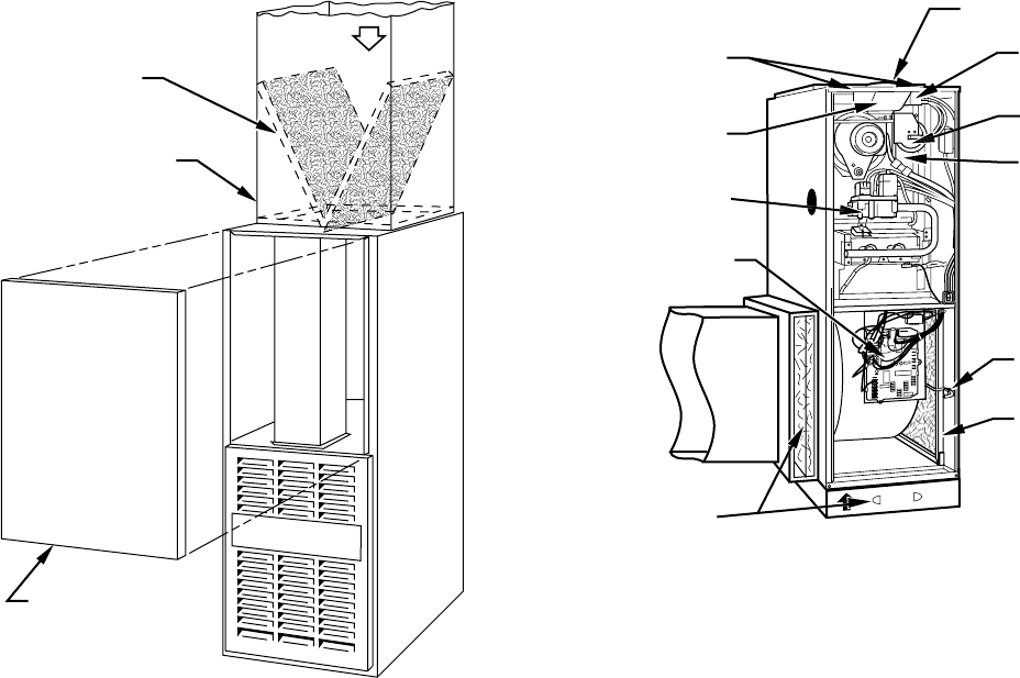
2. Upflow/Horizontal–filters installed in media cabinet adja-
cent to furnace (See Fig. 5.)
a. Turn off electrical supply to furnace
b. Remove filter cabinet door.
c. Slide filter out of cabinet.
d. If equipped with permanent, washable filter, clean filter
by spraying cold tap water through filter in opposite
direction of airflow. Rinse filter and let dry. Oiling or
coating of the filter is not recommended.
e. If equipped with factory-specified disposable media
filter, replace only with media filter having the same part
number and size.
f. Slide filter into cabinet.
g. Replace filter cabinet door.
h. Turn on electrical supply to furnace.
3. Upflow/Horizontal–filter(s) installed in side(s) and/or bot-
tom of blower compartment (See Fig. 5.)
a. Turn off electrical supply before removing blower and
control access doors.
b. Release filter retainer from clip at front of furnace
casing. (See Fig. 5.) For side return, clips may be used
on either or both sides of the furnace.
c. Slide filter out.
d. Clean filters by spraying tap water through filter from
opposite direction of airflow.
e. Rinse and let dry. Oiling or coating of filter is not
recommended or required.
f. Place filter in furnace.
g. Replace blower and control access doors and turn on
electrical supply to furnace.
II. BLOWER MOTOR AND WHEEL
The following items should be performed by a qualified service
technician:
For long life, economy, and high efficiency, clean accumulated dirt
and grease from blower wheel and motor annually.
The inducer and blower motors are pre-lubricated and require no
additional lubrication. These motors can be identified by the
absence of oil ports on each end of the motor.
Clean blower motor and wheel as follows:
1. Turn off electrical supply to furnace.
2. Remove blower access door.
3. Downflow only:
a. Disconnect vent connector from furnace flue collar. (See
Fig. 6.)
b. Remove internal vent pipe enclosure cover.
c. Disconnect and remove short piece of vent pipe from
within furnace.
d. Disconnect and remove vent pipe enclosure. Push bot-
tom side backward to release tabs.
NOTE: Vent pipe is SCREWED and RTV sealed to relief box.
4. Disconnect blower leads from furnace control. Note wire
color and location for reassembly. Also, disconnect auxil-
iary limit switch leads (downflow only, if present).
All other factory wires can be left connected, but field
thermostat connections may need to be disconnected de-
pending on their length and routing.
5. Remove 2 screws securing control and transformer support
to furnace.
6. Hang control and transformer support to front of furnace
casing.
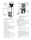
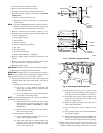
Fig. 4—Downflow Filter Arrangement
A88486
RETURN-AIR
PLENUM
AIRFLOW
ACCESS DOOR
INSTALLATION
POSITION
OF FILTERS
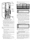
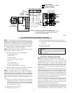
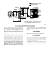
Fig. 5—Model 330JAV Upflow
A00293
BLOCKED
VENT
SAFEGUARD
FLUE
COLLECTOR
BOX
MOUNTING
SCREWS
RELIEF
BOX
CONTROL
FILTER
RETAINER
WASHABLE
FILTER
FURNACE
FLUE
COLLAR
PRESSURE
SWITCH
GAS
VALVE
C
OM
24V
HUMHUM
GRYW
WASHABLE
FILTER OR
DISPOSIBLE
MEDIA FILTER
IN FILTER
CABINET
—3—