


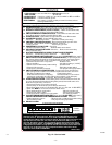


NOTE: A releasing agent such as PAM cooking spray or equiva-
lent (must not contain corn or canola oil, aromatic or halogenated
hydrocarbons or inadequate seal may occur) and RTV sealant
(G.E. 162, 6702, or Dow-Corning 738) are needed before starting
installation. DO NOT substitute any other type of RTV sealant.
G.E. 162 (P771-9003) is available through RCD in 3-oz tubes.
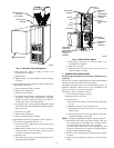
13. Reinstall relief box and inducer assembly.
NOTE: If inducer assembly gasket is damaged, use RTV sealant
to seal inducer assembly to collector box.
14. Reconnect wires to the following components:
a. Draft safeguard switch.
b. Inducer motor.
c. Pressure switches.
d. Limit overtemperature switch(es).
e. Gas valve.
f. Hot surface ignitor.
g. Flame-sensing electrode.
h. Flame rollout switch(es), if applicable.
15. Reinstall internal vent pipe and enclosure on downflow
furnaces only by reversing items 4a through 4c.
NOTE: A releasing agent such as PAM cooking spray or
equivalent (must not contain corn or canola oil, aromatic or
halogenated hydrocarbons or inadequate seal may occur) and RTV
sealant (G.E. 162, 6702, or Dow-Corning 738) are needed before
starting installation. DO NOT substitute any other type of RTV
sealant. G.E. 162 (P771-9003) is available through RCD in 3-oz
tubes.
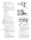
16. Reinstall vent connector to furnace flue collar. After fully
assembling vent connector to furnace flue collar, securely
fasten vent connector to flue collar with 2 field-supplied,
corrosion-resistant, sheet metal screws located 180 degrees
apart and midway up the collar.
17. Replace blower access door only.
18. Turn power and gas to ON.
19. Set thermostat and check furnace for proper operation.
20. Verify blower airflow and speed changes between heating
and cooling.
21. Check for gas leaks.
22. Replace control door.
WARNING: Never use a match or other open flame to
check for gas leaks. Use a soap-and-water solution. A
failure to follow this warning could result in fire, personal
injury, or death.
IV. ELECTRICAL CONTROLS AND WIRING
NOTE: There may be more than 1 electrical supply to unit.
The electrical ground and polarity for 115-v wiring must be
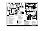
maintained properly. Refer to Fig. 9 and 10 for field wiring
information and to Fig. 11 for unit wiring information. If the
polarity is NOT correct, the furnace control will display rapid
flashing on the status LED and prevent heat operation. The control
system also requires an earth ground for proper operation of the
microprocessor.
With power disconnected to unit, check all electrical connections
for tightness. Tighten all screws on electrical connections. If any
smoky or burned connections are noticed, disassemble the connec-
tion, clean all parts and stripped wire, and reassemble properly and
securely. Electrical controls are difficult to check without proper
instrumentation; therefore, reconnect electrical power to unit and
observe unit through 1 complete operating cycle.
The 24-v circuit contains an automotive-type, 3-amp fuse located
on the main control. Any 24-v electrical shorts during installation,
service, or maintenance could cause this fuse to blow. If fuse
replacement is required, use ONLY a 3-amp fuse. The control will
display code 24 when fuse needs replacement.
The control in this furnace is equipped with an LED status light to
aid in installation, servicing, and troubleshooting. It can be viewed
through the sight glass or window on blower access door. The
control indicates status with the LED on continuously, rapid
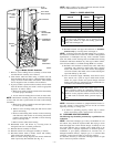
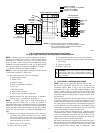
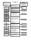
Fig. 9—Heating and Cooling Application Wiring Diagram
for Single-Stage Thermostats and Single-Speed Condensing Units
A99071
115-V FUSED
DISCONNECT
SWITCH
(WHEN REQUIRED)
JUNCTION
BOX
CONTROL
BOX
24-V
TERMINAL
BLOCK
TWO-WIRE
HEATING-
ONLY
FIVE
WIRE
1-STAGE THERMOSTAT TERMINALS
FIELD-SUPPLIED
FUSED DISCONNECT
CONDENSING
UNIT
FURNACE
COM
R
WYRG
C
GND
GND
GND
GND
GND
GND
FIELD 24-V WIRING
FIELD 115-, 208/230-, 460-V WIRING
FACTORY 24-V WIRING
FACTORY 115-V WIRING
208/230- OR
460-V
THREE
PHASE
208/230-V
SINGLE
PHASE
WHT
BLK
WHT
BLK
W/W1
W2
Y/Y2
G
NOTES: 1. Connect Y-terminal as shown for proper operation.
2. Some thermostats require a "C" terminal connection as shown.
3. If any of the original wire, as supplied, must be replaced,
use same type or equivalent wire.
—6—