


A97544
If inducer and burners continue to operate, check for 24v at the
gas valve. If 24v are present, verify that the thermostat is open
across R and W. If no voltage is present, turn the gas valve
control knob or switch to the OFF position. Replace gas valve.
Is indoor blower on ?
24v should be present across Com and W at furnace control. If
not, check for:
1. Open thermostat.
2. Open 24-v fuse (FU1) – Code 24.
3. Failed transformer.
If Code 23 is displayed, the pressure switch(es) is stuck closed.
Replace switch and/or check pressure tube for blockage.
System malfunction – Code 21.
115v should be present at the inducer motor. If so, replace inducer
motor. If not, check 115-v wiring.
Is Code 31 (high-gas-heat only), 32, 33, or 34 displayed? Check
code information label to diagnose.
Check polarity of 115-v power at J-box and control. Twinned
furnace polarities must match – rapid flashing LED.
Check ground continutity from J-box to control.
Check flame sensor microamps (4.0 nominal; 0.5 minimum for
control to recognize flame).
24v should be present across R and Com. If not, check for:
1. Open limit switch (LS) – Code 13 or 33.
2. Open flame rollout switch (FRS) – Code 13 or 33.
24v should not be present across R and G. If so, set thermostat
FAN to AUTO mode.
If not, check for:
1. Satisfied thermostat.
2. Open inlet gas pressure switch (when used).
3. Open pressure switch (LPS) – Code 32.
4. Open draft safeguard switch (DSS) – Code 32.
5. Open auxilliary limit (ALS)(downflow only) – Code 32.
6. Open 24-v fuse (FU1) – Code 24.
7. Open limit switch (LS) – Code 13 or 33.
8. Open flame rollout switch (FRS) – Code 13 or 33.
9. Check 115-v line voltage – LED off.
Check for sources of electrical noise interference (electronic air
cleaners, nearby TV, or radio antennas).
If Code 32 is displayed check for:
1. Open gas inlet pressure switch (when used).
2. Open pressure switch (LPS) and/or tube – Code 32.
3. Open draft safeguard switch (DSS) – Code 32.
4. Open auxiliary switch (ALS)(downflow only) – Code 32.
5. Check all low-voltage wiring connections.
115v should be present at the ignitor. If so, replace the ignitor; if not,
check 115-vac wiring to ignitor.
LPS, DSS, or ALS open while HPS if closed (high-gas-heat only) –
Code 43.
Is the gas valve control knob or switch in the OPEN or ON position?
24v should be present across the gas valve terminals C and M/P
(and C and HI for high-stage gas test) during the 7 sec ignition
trial. If not, check all low-voltage wiring connections to valve.
If 24v are present, and main gas does not flow:
1. Supply pressure between 4.5- and 13.6-in. wc. If not, adjust
supply pressure.
2. If supply pressure is between 4.5- and 13.6-in. wc, replace gas
valve.
Check ignitor position.
Check burner carryover gap.
Check gas supply pressure (4.5-in. wc minimum).
Check manifold pressure (1.3- to 1.7-in. wc for low-stage gas;
3.2- to 3.8-in. wc for high-stage gas).
Check for proper orifice size.
Control will attempt to light burners 4 times (approximately 1 minute
between attempts – Code 34). Voltage is present at the gas valve for 7
sec during each ignition trial. System will lockout after 4 attempts.
115v should be present at the blower motor. If so, check capacitor.
If capacitor is OK, replace blower motor. If 115v are not present at
the blower motor, check all 115-v wiring to motor.
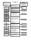
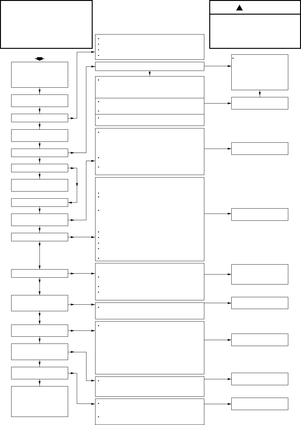
Cycle 115-v power
off for 3 sec, then on.
Continuous LED?
Draft inducer motor starts.
Is Code 22 displayed?
15-sec inducer pre-purge.
Set thermostat to call for heat.
Set FAN to AUTO mode.
Turn thermostat OFF.
On furnace control, note current
settings for setup switches 1 (SW-1)
and 2 (SW-2) then set SW-1 to OFF
and SW-2 to ON.
If LED is flashing rapidly, check line voltage polarity.
If Code 24 is displayed, check for blown fuse.
If LED is OFF, check line voltage and 24-v transformer.
If Code 45 is displayed, replace control.
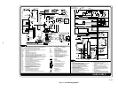
TROUBLESHOOTING
GUIDE
NOTES:
WARNING
ELECTRICAL SHOCK HAZARD
ONLY QUALIFIED AND TRAINED
SERVICE PERSONNEL SHOULD
PERFORM THIS PROCEDURE
!
Flame present when not normal.
Replace gas valve.
Ignitor warms up and glows
orange/yellow; 17-sec warm-up.
START
Yes
No
Yes
Main burners ignite.
Yes
No
Yes
Main burners stay on.
Turn thermostat to OFF; gas valve
shuts off burners; 5-sec inducer
post purge.
Indoor blower motor stops after
90, 135, 180, or 225 sec.
Yes
Yes
Furnace runs until call for
heat ends.
Yes
No
No
No
No
No
No
No
Indoor blower motor starts on
heating speed after 45-sec
warm-up period.
No
Yes
Yes
Yes
Yes
Yes
No
Replace control only if all checks
are OK.
No
Replace control only if Code 45 is
displayed, or if all checks are OK.
No
No
Replace control if Code 45 is dis-
played, or if all checks are OK.
Clean flame sensor if microamps
are below nominal.
No
Replace control only if Code 45 is
displayed, or if all checks are OK.
No
Replace control only if Code 45 is
displayed, or if all checks are OK.
No
Replace control only if Code 45 is
displayed, or if all checks are OK.
No
Replace control only if Code 45 is
displayed, or if all checks are OK.
No
Refer to information label on blower compartment door
for procedure for use of LED status codes and problem
solving suggestions.
LED indicator is viewed through window in blower
compartment door.
If 115-vac power is de-energized or interrupted during a
call for heat, the indoor blower will run for 90 sec before
a gas heating cycle begins – Code 12.
After replacing any component, verify correct operating
sequence.
1.
2.
3.
4.
Heating sequence of operation
complete. Remove blower door,
move setup switch 1 (SW-1) to ON
position and repeat process to check
high-stage gas heat operation.
(When finished return SW-1
and
SW-2 to original desired settings.)
No
24v should be present across R
and Com. If not, check for:
Open flame rollout switch
(FRS) – Code 33.
Open limit switch (LS) –
Code 33.
Check all low-voltage wiring
connections.
1.
2.
3.
Replace control only if Code 45 is
displayed, or if all checks are OK.
—10—