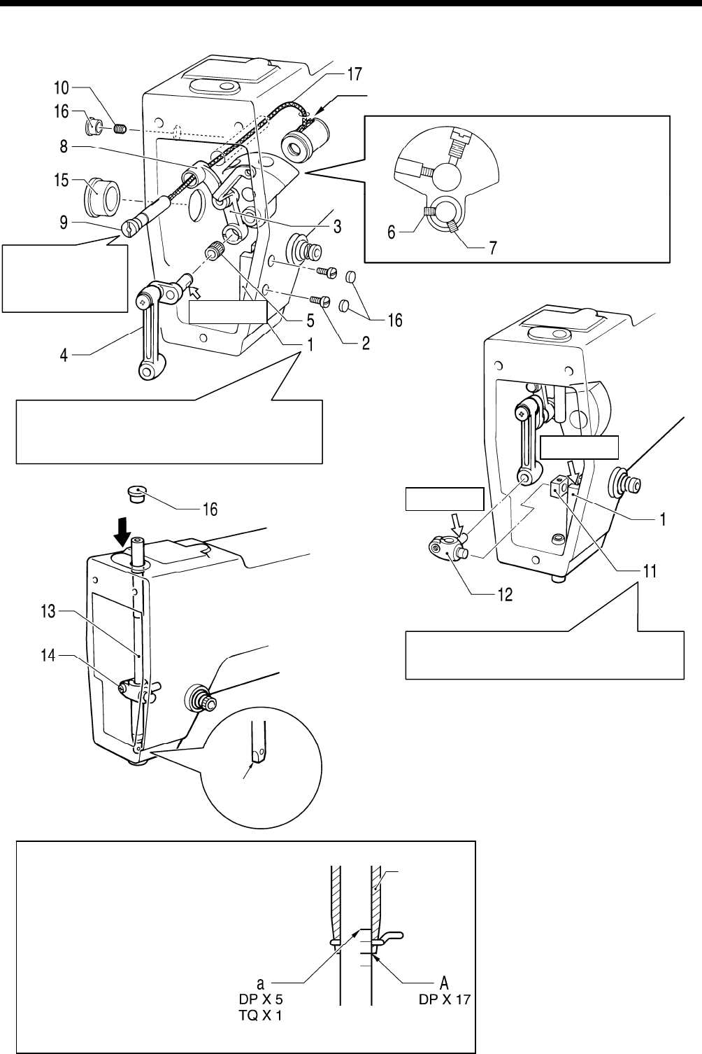
4. ASSEMBLY
4-11. Needle bar mechanism
Oil supp
ly hole
3392Q
Align th
e set screw with
the screw stop.
KE-430B, 430C series
82
Press the thread
take-up support shaft
gently while tightening
the set screw.
3393Q
Apply grease.
After securing the needle bar, position the
ne
edle bar guide so that the machine pulley
turns smoothly, and then tighten the screws.
Apply grease.
Apply grease.
Fit the chamfering side of the slide block
into th
e groove on the needle bar guide.
1. Needle bar guide
2. Scre
ws
[2 pcs: Temporarily tighten]
3. Thread take-up lever
4. Needle bar connecting rod
Cut section
5. Ne
edle bearing
6. Set screw
3394Q
7. Set
screw
A
lign the needle bar so that
reference line A (the second
lowest reference line on the
needle bar) or reference line a
(top reference line) is aligned
with the lower edge of the
needle bar bush when the
machine pulley is turned to raise
the needle bar from its lowest
position, and then set the cut
section so that it is facing
forward and tighten the screw.
8. Th
read take-up support
Needle bar
9.
Thread take-up support shaft
bush
10. Set
screw
11. Slide block
12. Needle bar clamp
13. Needle bar [Insert from above]
14. Screw
15. Oil cap
16. Rubber caps [4 pcs]
17. Wick [Insert into oil supply
hole]
3395Q


