8. ELECTRIC MECHANISM
Erro
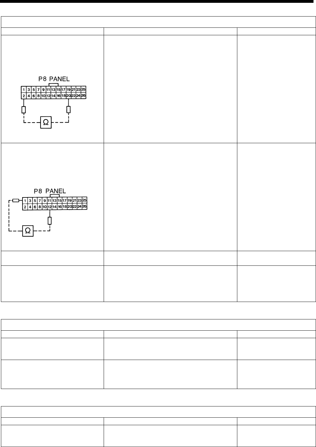
r status #11 The TEST indicator does not light when the TEST switch is pressed.
Probable causes Check/ repair/ adjust Parts to be replaced
1. TEST switch and its cord are
defective.
• Separate P8 (PANEL) connectors on the
main circuit board, and measure the
resistance between pins 2 and 20 in the
connector on the cord with the polarity
shown in the left figure.
(Use of a digital meter is prohibited.)
If the resistance is normally , or the
needle oscillates at its maximum limits
when the TEST switch is pressed, the
TEST indicator and its cord are not
defective.
(KE-430*, 431*, 432*, 433B,
434*, 435*, 484C, BE-438*)
KE-430B, 430C series
185
Pa
nel PCB or panel
cable assembly
2. TEST indicator and its cord
are defective.
(KE-430*, 431*, 432*, 433B,
434*, 435*, 484C, BE-438*)
• Measure the resistance between pins 1
and 12 with the same method as above.
If the needle oscillates at its maximum
limits, the TEST indicator and its cord are
not defective.
Panel PCB or panel
cable assembly
Red
Black
3. Main circuit board defective
Main circuit board
3645Q
3644Q
Red
Black
4. Panel PCB defective
(KE-436B, 436C)
• Check that P20 (RSPORT) connectors of
the main circuit board and P5 (DRV)
connectors of the panel circuit board are
plugged in.
Panel circuit board
Error status #12 The feed mechanism does not slowly move stitch by stitch during test sewing.
Probable causes Check/ repair/ adjust Parts to be replaced
1. Foot switch and cord defec-
tive
• See #7.
2. Incorrect memory switch
setting
• Set memo-08 to OFF.
(For the BE-438B and 438C, the default
setting is ON.)
• Set memo-0E to OFF.
Error status #13 Quick feeding cannot be performed during test sewing.
Probable causes Check/ repair/ adjust Parts to be replaced
1. Foot switch and cord defec-
tive
• See #7.


