4. ASSEMBLY
4. ASSEMBLY
KE-430B, 430C series
54
3329Q
Apply grease.
Apply grease.
Apply grease.
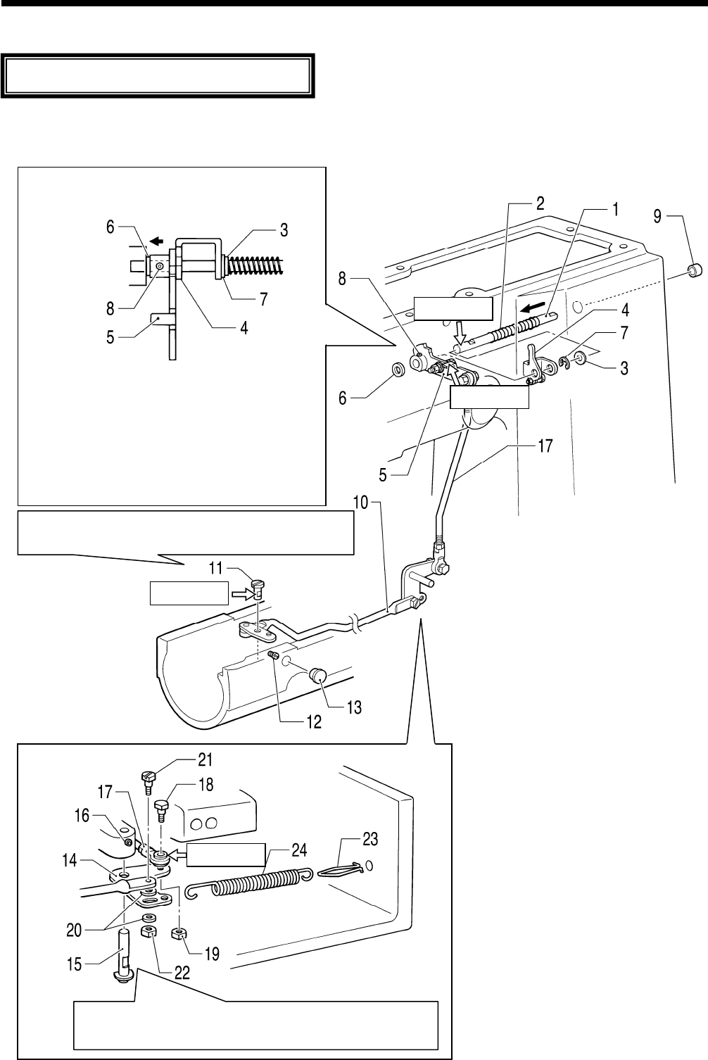
Assemble each part in order of the numbers.
Apply
grease to the required places when reassembling the parts and once every two years.
4-1. Thread trimmer mechanism (1)
Tighten the set screw on the screw flat while
lightly pressing the lever shaft downward.
Apply grease.
Tighten the set screw on the screw flat while lightly
pressing the thread trimmer lever shaft upward.
1.
Driving lever guide shaft
Install the retaining ring between the thread
release driving lever assembly and the
washer.
3328Q
Pla
ce the cushion against the edge of the
arm, set the various parts so that there is no
gap between them as shown in the
illustration, and then tighten the set screw as
far as the screw stop.
Adjust the position of the thread driving lever
assembly while referring to “5-20. Adjusting
the position of the thread trimming link
mechanism”.
2. Spri
ng
3. Washer
4. Thread release driving lever assy
5. Thread driving lever assy
6. Cushion
7. Retaining ring
8. Set screw
9. Rubber cap
Tilt the machine head.
10. Connecting rod lever assy
11. Lever shaft
12. Set screw
13. Rubber cap
14. Thread trimmer lever
15. Thread trimmer lever shaft
(with washer and retaining ring)
16. Set screw
17. Thread trimmer rod assy
18. Shoulder screw
19. Nut
20. Washers [2 pcs]
3330Q
21. Sh
oulder screw
22. Nut
23. Spring hook
24. Spring


