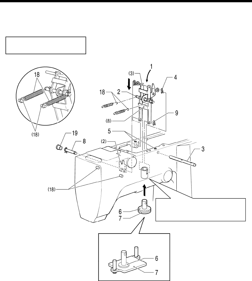
4. ASSEMBLY
4-5. Work clamp lifter mechanism (Solenoid specifications)
When assembling, apply grease to the required places while referring to “4-5-1. Applying grease”.
KE-430B, 431B, 433B, 434B
KE-430C, 4
31C, 434C
Secure link shaft, A using the set
scre
w so that link, B (8) is centered
in the bush.
<KE-433B, 434B, 434C>
3351Q
1.
Work clamp lifter link-related parts [Insert from above the arm]
2. Link shaft, B [Place into the forked section of the thread wiper driving lever (2)]
3. Link shaft, A [Pass through the washer and link A (3)]
4.
Snap pins [2 pcs: Attach to both ends of link shaft A]
5. Set screws [2 pcs]
6
. Work clamp lifter stopper rubber
7. Work clamp plate [Insert from below the arm]
8. Link shaft, C [Pass through link B (8) and the work clamp plate]
9. Snap pins [2 pcs: Attach to both ends of link shaft C]
10. Presser solenoid assy [Insert from above the arm]
KE-430B, 430C series
65


