


9
Concrete Slab
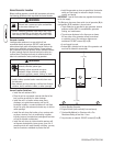
At the appropriate location, construct a concrete slab (28 day
compression strength of 3000 psi (200 MPa)) minimum
5 inches thick and 6 inches wider than the enclosure on
all sides. Strengthen slab with No. 6 reinforcing bars (on
12” centers) or 8 ga. steel wire fabric (6” centers). Avoid
placing reinforcement in entrance stub-up area.
Attach unit to slab with 5/16” diameter (minimum) masonry
anchor bolts long enough to retain the unit.
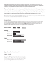
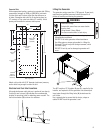
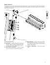
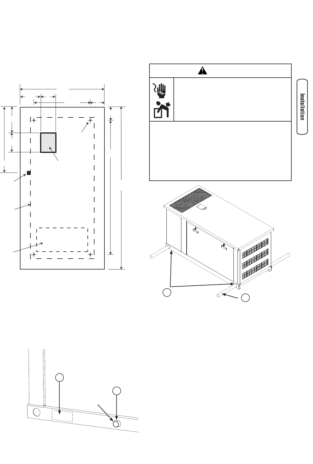
Electrical and Fuel Inlet Locations
A through-slab power cable stub-up is preferred (see above).
If stub-up’s are not used, (A) indicates the recommended
location for punching holes for attaching power conduit. The
fuel inlet connector (B) is shown for reference.
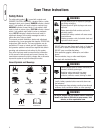
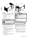
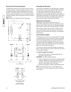
Lifting the Generator
The generator weighs more than 1,700 pounds. Proper tools,
equipment and qualified personnel should be used in all
phases of handling and moving the generator.
WARNING
Hazardous Voltage
Contact with power lines can cause electric
shock or burn.
Lifting Hazard / Heavy Object
Can cause muscle strain or back injury.
DO NOT contact any power lines when using required
lifting/hoisting equipment.
DO NOT lift or move generator without assistance.
Use lifting pipes or straps as described in Lifting the
Generator. The unit may shift during movement, which
can cause injury.
DO NOT lift unit by roof as damage to generator will
occur.
•
•
•
•
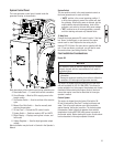
Two 60” lengths of 2” Schedule 40 pipe (B), supplied by the
installer, are required to lift the generator onto cement pad.
Insert pipes through the lifting holes (A) located near the
unit’s base.
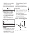
Use a spreader bar to ensure that the chains, straps or
cables DO NOT touch the generator’s roof.
B
A
B
A
49”
19”
108”
92”
53”
9.5”
7”
7.38”
34.25”
10.13”
8”
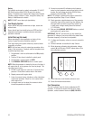
Power Cable
Stub-in
location
Fuel Inlet
Port
Enclosure
Base
Slab Top VIew
Exhaust
Opening
(shown for
reference)
Anchor bolt
position
(4 places)
1” Female NPT