


7
Installation
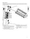
Equipment Description
This product is intended for use as an optional home
generator system which provides an alternate source
of electric power and to serve loads such as heating,
refrigeration systems, and communication systems that,
when stopped during any power outage, could cause
discomfort or inconvenience. This product does not qualify
for emergency standby as defined by NFPA 70 (NEC).
Customer Responsibilities
• Read and follow the instructions given in the Operator’s
Manual, especially the section regarding selecting
essential circuits.
• Follow a regular schedule in maintaining, caring for
and using your home generator, as specified in the
Operator’s Manual.
Installer Responsibilities
• Read and observe the safety rules.
• Install only an UL approved transfer switches that is
compatible with the home generator.
• Read and follow the instructions given in this
Installation and Start-up Manual.
IMPORTANT: The system is equipped with a water heater
that is activated when ambient temperature is less than 80°F
AND utility power is present at the transfer switch.
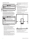
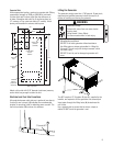
Unpacking Precautions
The unit is shipped ready for installation on a prepared
reinforced cement slab or engineered base. Avoid damage
from dropping, bumping, collision, etc. Store and unpack
carton with the proper side up, as noted on the shipping
carton.
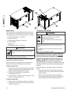
Delivery Inspection
After removing the carton, carefully inspect the home
generator for any damage that may have occurred during
shipment.
IMPORTANT: If loss or damage is noted at time of delivery,
have the person(s) making delivery note all damage on the
freight bill and affix his signature under the consignor’s
memo of loss or damage. If loss or damage is noted after
delivery, separate the damaged materials and contact the
carrier for claim procedures. Missing or damaged parts are
not warranted.
Shipment Contents
The home generator system is supplied with:
• Home generator
• Fully-serviced coolant system
• Fully-serviced oil/lubricating system
• UL569/CSA8.3-listed flexible fuel hook-up
• Installation and start-up manual
• Operator’s manual
• Engine operator’s manual
• Installation checklist
• Two access door keys
• One spare 15A fuse
• 10 Pole control panel connector
• Remote LED indicator kit (red LED/plate/screws)
Not Supplied:
• 650 CCA starting battery (NOT deep-cycle)
• Connecting wire and conduit
• Fuel supply valves/plumbing
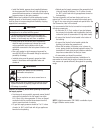
Required Specialty Tools/Equipment
• Two 60” lengths of 2” Schedule 40 pipe (NOT conduit)
• Lifting straps, chains or cables
• Hole punches for 7 ga steel
• Torque screwdriver, 5 to 50 inch-pound range
• Ignition Timing Light
• Air Fuel Ratio Meter (O2 Sensor and Analyzer)