


14 BRIGGSandSTRATTON.COM
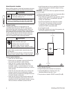
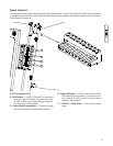
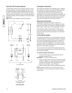
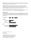
Generator AC Connection System
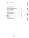
A single-phase, three-wire AC connection system is used in
the home generator. The stator assembly consists of a pair
of stationary windings with two leads brought out of each
winding. The junction of leads T2 and T3 forms the neutral
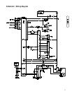
lead, as shown schematically and as wiring diagram below. A
complete schematic and wiring diagram can be found later in
this manual.
NOTE: Neutral is not bonded to ground at generator.
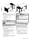
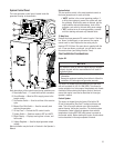
Grounding the Generator
Ground the home generator per applicable codes, standards
and regulations. There are two generator GND lug locations.
The one inside the alternator junction box next to the
circuit breaker is the primary lug and should meet most
applications. The second generator GND lug is located on the
frame below the generator circuit breaker cover, and should
ONLY be used for a ground rod located at the generator, if
required by local codes. See Controls for location.
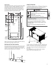
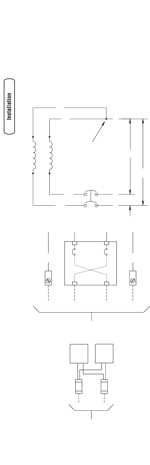
Utility Circuit Connection
“240V Utility” leads must be routed in conduit. The
“240V Utility” leads deliver power to the generator’s circuit
board and water heater. This power also charges the battery.
When power on these leads is lost, the generator will start.
Using installer-supplied minimum 300V, 14 AWG copper
wire, connect each ten-amp fuse terminal in the alternator
junction box to the ten-amp fuse terminals in the automatic
transfer switch.
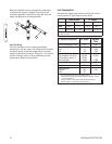
Fault Detection System
The generator may have to run for long periods of time with
no operator present. For that reason, the system is equipped
with sensors that automatically shut down the generator in
the event of potentially damaging conditions, such as low
oil pressure, high water temperature, over speed, and other
conditions. Refer to Fault Detection System in the Operator’s
Manual for more detailed information.
The owner will use the remote LED indicator to observe the
status of the home generator system. Consult with the owner
for a convenient location.
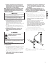
To install the remote LED indicator:
1. Push the LED through the mounting plate from the
front until it snaps in place.
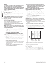
IMPORTANT: The LED is polarity sensitive.
2. Using provided 10 pole connector and installer-supplied
minimum 18AWG wire, connect the remote LED to the
generator control board +LED and GND connection.
Use wire nuts to attach wire to LED leads.
3. Attach mounting plate to installer-supplied electrical box.
NOTE: Locate the electrical box in an area visible by the
home owner such as near a garage door opener or security
control panel.
10 A10 A
240 VAC
Control
Board
Water
Heater
To Transfer Switch
Utility Fuse Connection
N G
T4 T1
Circuit
Breaker
Neutral
Neutral
Line 1 Line 2 Ground
Ground
To Transfer Switch
T2
120 V
120 V
240 V
T4
T1
T3
Neutral
Circuit
Breaker
Power Winding
Neutral
To Transfer Switch
Control
Board
Ground
Power Winding
Circuit
Breaker
Line 1
Water
Heater
Neutral
Neutral
To Transfer Switch
Utility Fuse Connection
Line 2
Ground
Circuit
Breaker