


34
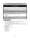
SECTION IX: OPERATING INSTRUCTIONS
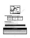
WARNING
Water heaters are heat-producing appliances. To avoid damage or injury there must be no materials stored against
the water heater or direct vent system, and proper care must be taken to avoid unnecessary contact (especially by
children) with the water heater and direct vent system. UNDER NO CIRCUMSTANCES SHOULD
FLAMMABLE MATERIALS, SUCH AS GASOLINE OR PAINT THINNER BE USED OR STORED IN THE
VICINITY OF THIS WATER HEATER OR IN ANY LOCATION FROM WHICH FUMES COULD REACH
THE WATER HEATER.
Installation or service of this water heater requires ability equivalent to that of a licensed tradesman in the field
involved. Plumbing, air supply, venting, gas supply and electrical work are required.
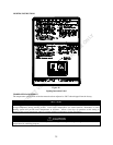
Light the unit in accordance with the operating instructions label attached to the water heater.
Under no circumstances should the input rate exceed the input rate shown on the water heater rating plate. Over
firing could result in damage or sooting of the water heater.
If the unit is exposed to the following, do not operate water heater until all corrective steps have been made by a
factory authorized independent service contractor or qualified service professional.
1. Flooding to or above the level of the burner or controls
2. External firing
3. Damage
4. Firing without water
5. Sooting
NEVER OPERATE THE WATER HEATER WITHOUT FIRST BEING CERTAIN IT IS FILLED WITH
WATER AND A TEMPERATURE AND PRESSURE RELIEF VALVE IS INSTALLED IN THE RELIEF
VALVE OPENING OF THE WATER HEATER.
GENERAL INSTRUCTIONS
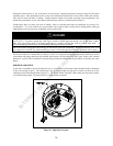
TO FILL THE WATER HEATER
1. Close the water heater drain valve by turning the knob or valve stem clockwise. If alternative water
connections are provided but not used, make certain they are plugged (i.e. rear connections).
2. Open the cold water supply shut-off valve.
3. Open several hot water faucets to allow air to escape from the system.
4. When a steady stream of water flows from the faucets, the water heater is filled. Close the faucets and
check for water leaks at the water heater drain valve, combination temperature and pressure relief valve and
the hot and cold water connections.
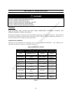
SEQUENCE OF OPERATION
1. A call for heat from thermostat
2. Blower ON
3. Pressure switch proves blower operation
4. Blower pre-purge
5. Igniter warm-up
6. Main burner ON
7. Flame signal confirmed
8. Thermostat satisfied
9. Main burner OFF
10. Blower post-purge
INTERNET VERSION FOR REFERENCE ONLY