


19
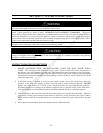
NOTICE
Before beginning installation of any vent pipe, read the vent pipe manufacturer’s installation instructions.
Water heater must be protected from freezing downdrafts during shutdown periods
Provide protection of the building materials from degradation by flue gases from the exhaust vent terminal.
VENTING
The venting instructions must be followed to avoid restricted combustion or recirculation of flue gases. Such
conditions cause sooting or risks of fire and asphyxiation.
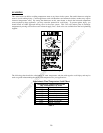
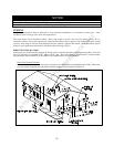
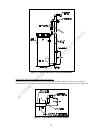
This water heater can be installed as either a direct vent system or power vent (air from inside) system. If it is
installed as a direct vent system, then the air intake and the exhaust vent are piped to the outside. If a power vented
system is used, then air is drawn from inside and only the exhaust is piped to the outside. Determine which system
is best for your application and install as described in the following sections.
DIRECT VENT INSTALLATION
Venting may be run horizontally through an outside wall or vertically through a roof through using either 3 inch (7.6
cm) or 4 inch (10.2 cm) diameter PVC, ABS or CPVC pipe. This water heater is supplied with a screened intake
and exhaust 90° elbow referred to as the exhaust vent terminal and the air intake terminal.
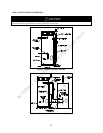
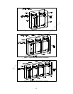
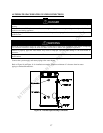
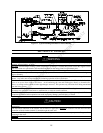
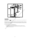
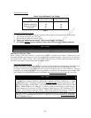
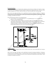
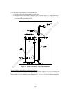
Direct Vent Terminal Location
Plan the vent system layout so that proper clearances are maintained from plumbing and wiring. Before the
vent is installed, determine the vent pipe termination location as shown below in Figure 12.
Figure 12. Vent Terminal Location
INTERNET VERSION FOR REFERENCE ONLY