


21
NOTICE
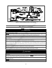
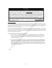
This unit can be vented using only PVC (Class 160, ASTM D-2241 Schedule 40, ASTM D-1785;
or Cellular Core Schedule 40 DWV, ASTM F-891), Schedule 40 CPVC (ASTM F-411), or ABS
(ASTM D-2661) pipe. The fittings, other than the TERMINATIONS should be equivalent to PVC-
DWV fittings meeting ASTM F-2665. (Use CPVC fittings, ASTM F-438 for CPVC pipe and ABS
fittings, ASTM D-266/3311 for ABS pipe.) If CPVC or ABS pipe and fittings are used, then the
proper cement must be used for all joints, including joining the pipe to the Termination (PVC
material). PVC materials should use ASTM –D2564 grade cement; CPVC materials should use
ASTM F-493 grade cement; and ABS materials should use ASTM D-2235 grade cement.
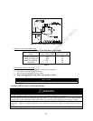
For water heaters in locations with high ambient temperatures (above 100°F) and/or insufficient
dilution air, it is recommended that CPVC or ABS pipe and fittings (MUST USE SUPPLIED
VENT TERMINAL) be used.
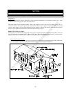
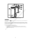
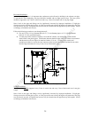
Horizontal Installation:
In a horizontal application, it is important that condensate not be allowed to buildup in the exhaust vent pipe.
To prevent this from happening the pipe should be installed with an slight upward slope so the condensate will
run back toward the water heater. The vent system should be supported every 5 feet of vertical run and every 3
feet of horizontal run of vent pipe length.
Stress levels in the pipe and fittings can be significantly increased by improper installation. If rigid pipe
clamps are used to hold the pipe in place, or if the pipe cannot move freely through a wall penetration, the pipe
may be directly stressed, or high thermal stresses may be formed when the pipe heats up and expands. Install
accordingly to minimize such stresses.
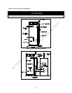
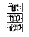
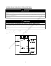
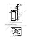
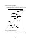
Follow the following procedure to vent through the wall:
1. Cut two 3 1/2 in. (8.9 cm) diameter holes (for 3” (7.6 cm) diameter pipe) or 4 ½” (11.4 cm) diameter
holes (for 4” (10.2 cm) diameter pipe) in the wall with the centerline hole distances at least 18” (45.72
cm) apart in the location where the exhaust vent and air intake terminals will exit the outside wall if
vented on the same wall.
2. Use the proper PVC cement to secure the 90° exhaust vent and air intake terminals provided with the
water heater to the plastic pipes. The distance between the back edge of the 90° exhaust vent terminal
and the exterior wall (see Figure 13) must be 6 inches (12.7 cm) more for the exhaust vent terminal
than the air intake terminal. Use the proper cement or sealant and assembly procedures to secure the
vent connector joints between the terminal and the blower outlet. Provide support brackets for every
3 feet (.91 m) of horizontal vent.
INTERNET VERSION FOR REFERENCE ONLY