


29
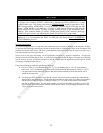
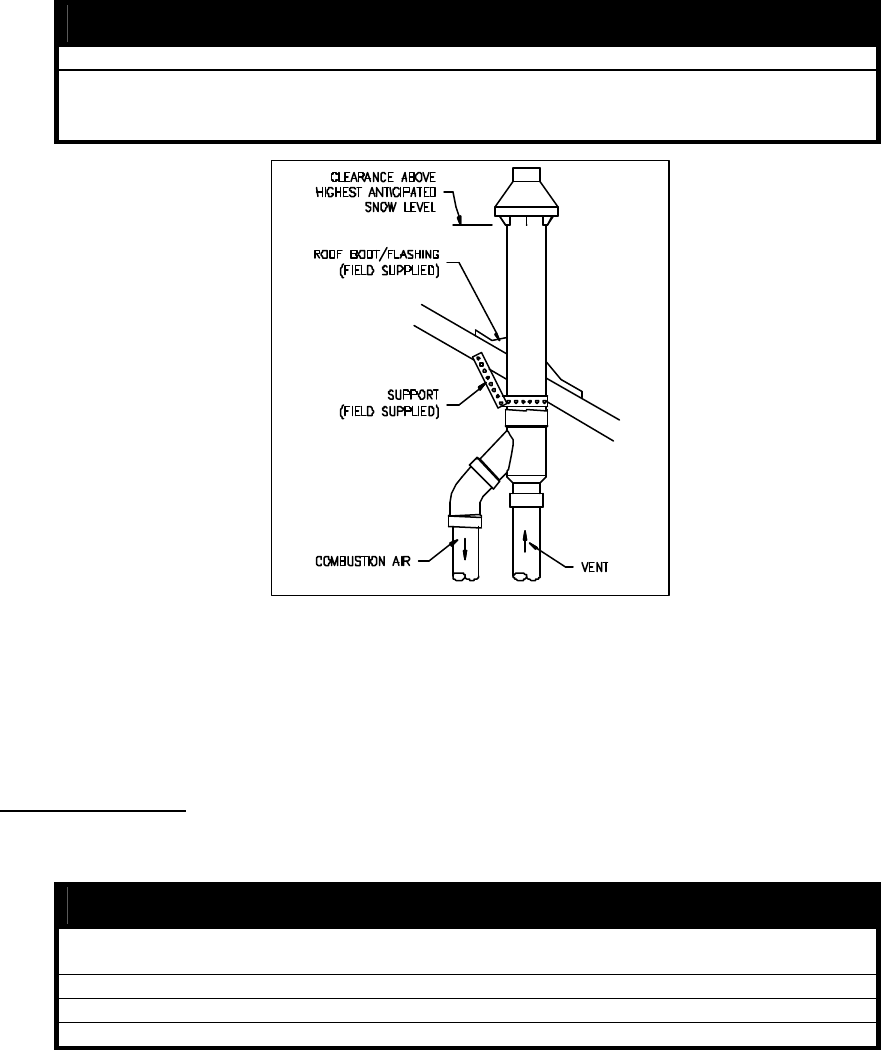
5. Install concentric Y fitting and pipe assembly through the structure’s hole and field-supplied roof
boot/flashing. Do not allow insulation or other materials to accumulate inside pipe assembly when
installing through the hole.
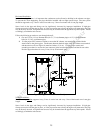
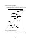
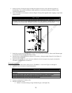
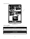
6. Secure assembly to roof structure as shown in Figure 22 using field-supplied metal strapping or equivalent
support material.
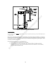
NOTICE
Ensure termination height is above the roof surface or anticipated snow level. Figure 22.
If assembly is too short to meet height requirements, the 2 pipe supplied in the kit may be replaced
by using the same diameter pipe. DO NOT extend the overall dimension by more than 60 in.
See Fig. 19.
Figure 22. Concentric Vent Roof Top Attachment
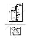
7. Install rain cap and small diameter pipe assembly in roof penetration assembly. Ensure small diameter pipe
is cemented and bottomed in Y concentric fitting.
8. Cement heater combustion-air and vent pipes to concentric y fitting assembly (Figure 20). See Figure 22
for proper pipe attachment.
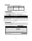
9. Operate heater through one cycle to ensure combustion-air and vent pipes are properly connected to
concentric vent termination connections.
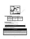
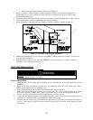
Horizontal Installation :
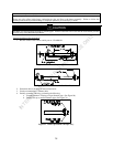
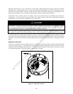
1. Become familiar with coaxial vent kit part no. 239-44069-01. As shown in Figures 19 through 21.
2. Determine the best location for the termination kit.
NOTICE
Position termination where vent vapors will not damage plants/shrubs or air conditioning
equipment.
Position termination where vent vapors will not be adversely effected by wind condition.
Position termination where it will not be damaged or be subjected to foreign objects.
Position termination where vapors will not be objectionable.
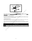
3. Cut the recommended 5” diameter hole.
4. Partially assemble vent kit.
a. Cement Y concentric fitting to larger diameter kit pipe. (See Figure 20).
INTERNET VERSION FOR REFERENCE ONLY