


27
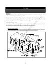
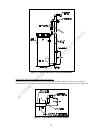
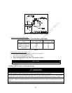
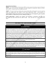
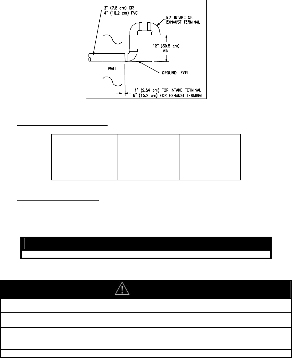
Figure 18. Vent Terminal (Low Ground Clearance)
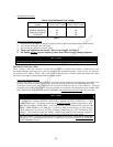
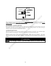
Maximum Vent Length Determination
Power Vent Maximum Vent Length
Model
Number
Max Vent Length (feet)
3" PVC, CPVC, or ABS
Max Vent Length (feet)
4" PVC, CPVC, or ABS
EF60T125, EF100T150 120 170
EF60T150, EF100T199 100 150
EF60T199, EF100T250
EF100T300
80
60
130
120
Table 4
Determining required vent length:
1. Determine the total length of straight vent pipe (in feet) required.
2. Add 5 feet of venting for every 90° elbow.
3. Add 2 ½ feet of venting for every 45° elbow.
4. Total vent length can not exceed “Max. Vent Length” in Table 4.
NOTICE
Do not include the 3” exhaust elbow or vent terminals in determining maximum vent length.
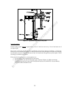
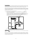
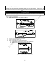
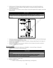
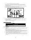
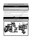
COAXIAL VENTING INSTALLATION PROCEDURE
WARNING
Improper installation, adjustment, service, or maintenance can cause
property damage, personal injury, or death.
Consult a qualified installer, service agency, or the gas supplier for information or assistance.
This kit must be used only for terminating this water heater. Do not use this termination kit for any other app
liance.
Using this kit on other appliances and/or water heaters can result in property damage, personal injury, or death.
DO NOT operate this water heater until the installation and assembly of this kit is complete and the piping
completed. Failure to complete installation before operation can result in property damage, personal injury, or
death.
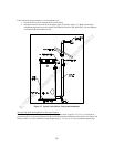
Before beginning any installation, be sure the main electrical disconnect switch is in the OFF position. Electrical
INTERNET VERSION FOR REFERENCE ONLY