


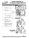

Thermostat Sensor (Thermister) Replacement Procedure
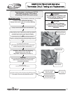
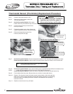
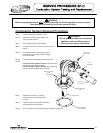
Step 5. Fold back insulation just in front of burner to
expose temperature sensor (see photo below).
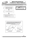
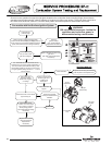
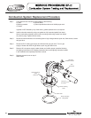
Step 6. Disconnect temperature sensor from
harness (see photos at right).
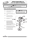
Step 7. Hot Surface Ignition Models: Remove temperature sensor (1-1/16" hex, deep well socket) from heater.
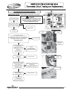
Direct Spark Ignition Models: Unclip sensor from well and pull sensor to remove, do not remove well.
Note: Using a deep well socket will allow room inside socket
for sensor connector and wires.
Step 8. Hot Surface Ignition Models: Apply thread sealing tape or applicable thread lubricant to threads of new
sensor. Install new thermostat sensor and Connect to wire harness from step 6.
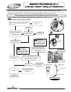
Direct Spark Ignition Models: Install new sensor completely into well and reinstall sensor clip.
Step 9. Fold insulation back into place. Be sure there are no wires in contact with burner.
Step 10. Restore 120 volt power supply and water supply to water heater, check and repair any
leaks found. Confirm proper operation following the lighting instructions on the lighting
instruction label or the lighting instruction located in the installation and operating
instruction manual.
Step 11. Replace surround cover on top of heater.
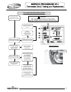
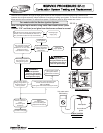
Step 1. Position main power switch to “OFF”
Step 2. Disconnect (unplug) water heater from
120 volt power source.
Step 3. Hot Surface Ignition Models: Drain water
heater down to a point below the top of the tank.
Step 4. Un-latch and remove top surround cover
from top of heater.
WARNING
120 volt potential exposure. Isolate the
appliance and reconfirm power is
disconnected using a multi-meter.
42
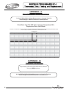
Sensor shown fully
inserted into well
Sensor clip shown
installed properly
Direct Spark Ignition Models
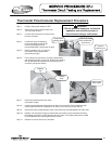
Disconnect sensor
from harness
Hot Surface Ignition Models
Insulation folded
back to expose
temperature sensor
42