


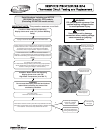
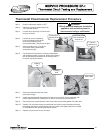

Thermostat Potentiometer Replacement Procedure
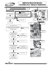
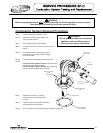
Step 4. Loosen set screw of adjusting
knob (small blade screw driver)
and remove adjusting knob
from potentiometer. (see photos at right)
Step 5. Remove retaining nut (½" wrench)
and washer from potentiometer.
(see photos at right)
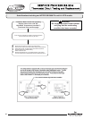
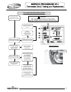
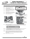
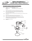
Step 6. From inside of surround area, remove potentiometer
with gasket from side of surround. Notice how indexing
tab on potentiometer assembles into locating hole of
surround. (see photos below)
Step 7. Disconnect potentiometer wire leads.
(see photo at right)
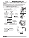
Step 8. Install new potentiometer with gasket into side of surround. Be sure to assemble with
indexing tab inserted into locating hole on side of surround (see photos above).
Step 9. Reconnect wires to potentiometer. Note: Wire leads are interchangeable with either wire.
Step 10. Restore 120 volt power supply to water heater and confirm proper operation following
the lighting instructions on the lighting instruction label or the lighting instruction located
in the installation and operating instruction manual.
Step 11. Replace surround cover on top of heater.
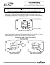
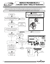
Step 1. Position main power switch to “OFF”
Step 2. Disconnect (unplug) water heater from
120 volt power source.
Step 3. Un-latch and remove top surround cover
from top of heater.
WARNING
120 volt potential exposure. Isolate the
appliance and reconfirm power is
disconnected using a multi-meter.
Temperature
Adjusting Knob
Indexing
Tab
Locating
Hole
41
Loosen set screw
with small blade
screw driver
Remove
retaining nut
Potentiometer
Wire Leads
41