


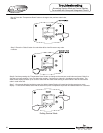
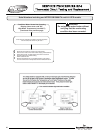
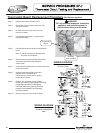
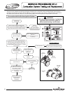
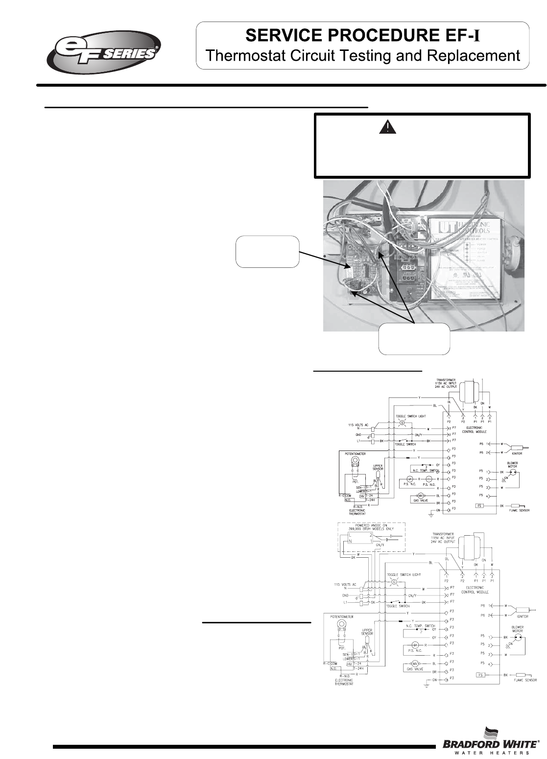
WIRING DIAGRAM
For models prior to
CF serial number
Step 5. Carefully disconnect all wires from thermostat
board.
Note: it may be necessary to identify wires
for proper re-connection.
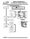
Step 6. Remove the two screws (Phillips head screw
driver) that secure thermostat board to
control panel.
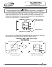
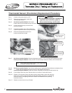
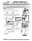
Step 7. Install new thermostat board to control panel using
screws from step 6.
Step 8. Carefully reconnect wiring per the wire
diagram below. Reconfirm wire
connections are correct prior to putting
heater back in service
Step 9. Restore 120 volt power supply to water
heater and confirm proper operation following
the lighting instructions on the lighting
instruction label or the lighting instruction
located in the installation and operating
instruction manual.
Step 10. Replace surround cover on top of heater.
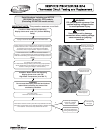
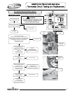
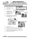
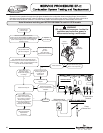
Thermostat Board Replacement Procedure (Hot Surface Ignition)
Step 1. Position main power switch to “OFF”
Step 2. Disconnect (unplug) water heater from 120
volt power source.
Step 3. Un-latch and remove top surround cover
from top of heater.
Step 4. Locate thermostat board on control panel.
(see photo at right)
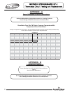
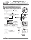
WIRING DIAGRAM
For models starting with
CF serial numbers and
later.
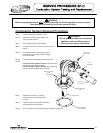
WARNING
120 volt potential exposure. Isolate the
appliance and reconfirm power is
disconnected using a multi-meter.
40
Thermostat
Board
Mounting
screw locations
40